9V Cc T2 50 Ce Vs eñal 0.5mA 10k


Q: Q2/A) Draw the basic construction of a n-channel JFET. B) Sketch the transfer curve defined by Ioss…
A: N channel JFET have p type substrate channel forms between gate and substrate and current flow from…
Q: Q5. The range of gain, K, for theclosed loop system K G(s)= that will cause the system to be stable…
A: We are authorized to answer one question at a time, since you have not mentioned which question you…
Q: Find the gain (Vout / Vin) of the circuit below. Note: VB voltage source is a DC source wwwn and do…
A:
Q: If VCE sa-0.3V, then transistor shown in the following circuit is saturated. 12V 32:2K2 RB B = ISC…
A:
Q: 2. For the following circuit assume g = 2.14 x10 mho , r = 40 ka +15 V a. Draw the small signal…
A: As per our company guidelines, We are supposes to answer only first 3 sub-parts. Amplifier: It…
Q: Q-4: A- Calculate the common-mode output voltage and A, voltage gain for the circuit below, where V…
A:
Q: Analyze the following Combinational circuit and Find F. Z 1 X I Highest A Priority 2 Encoder 3 MSB…
A:
Q: Plot the transfer curve for an n-Channel JFET Voltage divider circuit with VDD=23V R1=942 k-ohm,…
A: The solution is given below
Q: 4.2 An n-channel JFET has Vp= -5 V and Inss= 12 mA and is used in the circui! shown. The parameter…
A: For the given n-Channel JFET VDS and ID is determined as shown below
Q: For the network, determine re for a voltage gain of Av = -200. VoH 1 MQ -Vcc 4.7 ΚΩ Hf ovo B =90
A:
Q: 1. For the following circuit assuming ideal OpAmp, what resistor is needed for Rf to have a gain of…
A:
Q: What is the gain, V of the given circuit at a frequency of f = 60 Hz, given that R= 10 2 L=50 mH.…
A: Given : f=60 HzR=10 ΩL=50 mHC=200 μF
Q: PLease find the Transconductance value of the Transistors below a. μnCox = 250 μA/V², W/L=10,…
A: Transconductance gm is given as; gm = k'n WL VGS – Vth = μnCox WL VGS – Vth Substitute the…
Q: (b) Find the drain current ID for various values of VGs = 0V, -3 and -6 V. The value of VGs(OFF) =…
A:
Q: Determine Ix, Vy, v and i in the circuit shown below. -DA ЗА Žin ODv O Vy Ocv Ix 4 A
A: The given circuit diagram is: It is given that: C=0 D=3
Q: 05:for the multistage amplifier circuit shown below find Vo if Vi is 25µV with RL = 1kQ, RL=. %3D…
A:
Q: Determine the overall Voltage Gain Av and Current Gain of the circuit below given = 100, gm = 20…
A: The given circuit is hsown below: β=100, gm = 20 us, IDss = 10 mA and Vp = - 4V.
Q: Base emitter=0.7 v a- if Vce=3.4v what is r2 Vc,Ve,Vbc b- if R2=7k what is Ic Vce c-R2 change…
A: 10-1500100ib=VC
Q: For the inverting amplifier circuit shown below, find Rf for a gain of -5. RE 8 kN Vin Xa +
A: Operational Amplifier: A direct coupling amplifier that can increase the bandwidth of an input…
Q: ome work VcC fferential amplifier with Darlington input nsistors: RC1 Rc2 + Vod - If Rb=0 prove…
A: SOLUTION- (a) For , VCE, DC equivalent circuit will be input voltagesb shorted. By KVL,…
Q: B = 100 Va = 100 Find the Av = Vo / Vs
A:
Q: D1.31 Use Mason's gain rule to find the transfer function of each system of Figure DI.31. RG) 1 R(s)…
A:
Q: transistor has B=80 The intereledlrede copacitance Cbe=80PF Cbc=2 PF Cce=120PF Ncc be=4R2 LUF R, ike…
A:
Q: n Figure 3, R1 = 5 ohms, R2 = 10 ohms, and C = 0.4 F. Determine the transfer function between Vo and…
A:
Q: Q-4: A- Calculate the common-mode output voltage and A. voltage gain for the circuit below, where V;…
A:
Q: s1) a) What area does the circuit run in? Calculate the middle band voltage gain Av=? VA=303V,…
A:
Q: for the Circuit in Self bisa Configuration in JFET Shown below VD = When the IDss = 4.5mA VP = -51…
A:
Q: what is the transfer function of a Potentiometer with a gain Kp Of 1,5 v/had 4. K, K a) Find Oc /0;…
A:
Q: Given a common emiiter amplifier (Voltage Divider) with the following network: R1 = 22k, R2 = 6.8k,…
A:
Q: For the circuit shown below, if the voltage across Re is to be 250mV with a transconductance gm =…
A: For the circuit shown below If the voltage across RE is to be 25o mV with a transconducatnce gm=1/26…
Q: Find the Q-point values for the JFET with voltage-divider bias. Ip Ipss 5 mA VDD +12 V Rp 3.3 МО 1.8…
A:
Q: What is the Thévenin equivalent resistance of the given circult to the right of the dashed line?…
A:
Q: 0.1 For the circuit shown, calculate the Av and RE that required to get 5KHZ lower critical…
A:
Q: 0;: For the voltage-divider enhancement-type MOSFET configuration of Fig. below: (a) Determine Ipo…
A: Write the expression for the drain current,
Q: Q-5) Design the fixed-bias network to have an ac gain of 10. That is, determine the value of Rp. Rp…
A:
Q: +12 V Rc C3 100 N V out R1 680 N 10 μF RL 100 N Vin 10 μF REI 4.7 N R2 510 N C2 10 μF RE2 75 Ω B=125…
A: We will find out power gain for given circuit
Q: Rs 20V 本 6.8V
A:
Q: The Si transistor of the following figure has a-0.99, VEE= 4V and Vc=12V. i- If I-1.1 mA, find Ry.…
A: Given circuit: α=0.99VEE=4 VVCC=12 VIE=1.1 mAVCE=-7 V
Q: vcc 12V SRC RB 2.2kn C1 470k. C2 b 5.6µF Vo B = 100 Vi 5.6µF . ro = 00 RE 6800 What is the value of…
A:
Q: 2- Discuss when the state of active low of S and R two of them is zero o 2:23 äles VG
A:
Q: "Given a common emiiter amplifier (Voltage Divider) with the following network: R1 = 22k, R2 = 6.8k,…
A: DC analysis
Q: 1- Show that the output carry in a full adder circuit can be expressed as. Ci +1 = Gi + Pi Ci -(Gi…
A: Note: As per the company policy, we experts are allowed to answer only one question. Kindly post the…
Q: In an n-channel JFET biased by potential divider method.lt is desired to set the operating point at…
A:
Q: "Given a common emiiter amplifier (Voltage Divider) with the following network: R1 = 22k, R2 = 6.8k,…
A: To calculate the input impedance of Common Emitter amplifier (voltage divider)
Q: se the appropriate circuits to implement an output voltage given by Vout = 10 Vin + 4 Vin dt %3D
A:
Q: Q1. for the circuit shown, if the output peak voltage = 6 V. find VB? Vec 25 V Rc R 80 0 200 Ω 120 a…
A: Diode is in the forward biased for Vcc therefore it doesn't affect on the base Volage . voltage…
Q: "Given a common emiiter amplifier (Voltage Divider) with the following network: R1 = 22k, R2 = 6.8k,…
A:
Q: QUESTION 25 Find the value of Rf that will produce the closed loop gain of -230 R VinoW 10 kn oV out
A: Given, Ri=10 kΩVoutVin=-230
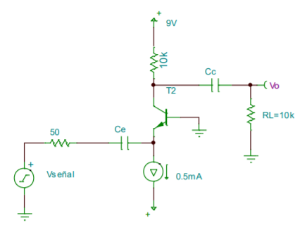
20. For β = 99, find the gain Vo / Vsignal.

Step by step
Solved in 2 steps with 2 images
