A 5 cm diameter potable water line is to be run through a maintenance room in a commercial building. Three possible layouts for the galvanized iron water line are proposed as shown in the figure. The bends are conventional threaded fittings. Select the option that minimizes losses and determine the pressure drop for a flow of 350 L/min. For the elbo losses use, hℓm =
A 5 cm diameter potable water line is to be run through a maintenance room in a commercial building. Three possible layouts for the galvanized iron water line are proposed as shown in the figure. The bends are conventional threaded fittings. Select the option that minimizes losses and determine the pressure drop for a flow of 350 L/min. For the elbo losses use, hℓm =

Automotive Technology: A Systems Approach (MindTap Course List)
6th Edition
ISBN:9781133612315
Author:Jack Erjavec, Rob Thompson
Publisher:Jack Erjavec, Rob Thompson
Chapter36: Electric Vehicles
Section: Chapter Questions
Problem 8RQ: Which of the statements about hydrogen is true? a. A hydrogen atom is one proton and two electrons....

Related questions

Question
A 5 cm diameter potable water line is to be run through a maintenance room in a commercial building. Three possible layouts for the galvanized iron water line are proposed as shown in the figure. The bends are conventional threaded fittings. Select the option that minimizes losses and determine the pressure drop for a flow of 350 L/min.
For the elbo losses use, hℓm =
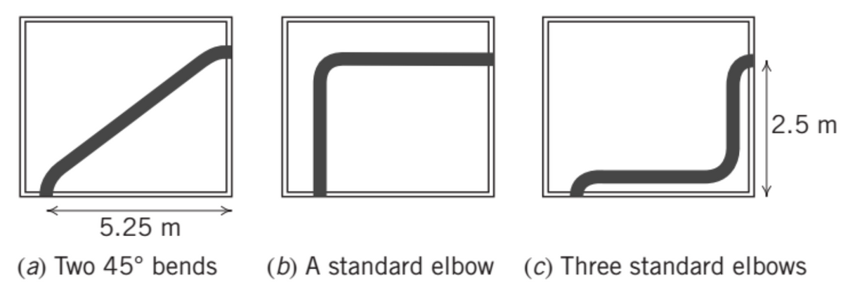
Transcribed Image Text:5.25 m
(a) Two 45° bends
2.5 m
(b) A standard elbow (c) Three standard elbows
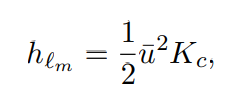
Transcribed Image Text:hem
1
H|2
u²Kc
2
Expert Solution
This question has been solved!
Explore an expertly crafted, step-by-step solution for a thorough understanding of key concepts.

This is a popular solution!

Trending now
This is a popular solution!

Step by step
Solved in 4 steps

Follow-up Questions
Read through expert solutions to related follow-up questions below.
Follow-up Question
Hi, I unfortunately cant see the full explanation, is there any way the writing could be condensed to show all of it on the screen?

Transcribed Image Text:Step 1: Given data and the parameters need to find out
Given: Pipe diameter, d = 5 cm = 0.05 mWater flow rate, Q=350 L/min
Step 2: 1) Calculation for the suitable layout which minimizes the losses
The average velocity of water through the pipe is, u =
OKA
Solution
||
元4
xd²
WAS THIS HELPFUL?
-
350 × 10-³
60
× 0.05²
π
-
-
350 × 10-³
60
3
-m³/sElevation difference betwee
Step 3:2) calculation of pressure drop in each layout
a Two 45° bends Applying Bernoulli's equation at the pipe inlet 1 and the pipe exit 2, Pg +Z₁ + V₂²
2.97 m/sUsing Loss coefficient data
-
P
+ Z₂ + 1/2/2
1 The head loss in the Two 45° bends is the minimum. Hence, the layout of two 45° bends should be s
Solution
Knowledge Booster


Learn more about
Need a deep-dive on the concept behind this application? Look no further. Learn more about this topic, mechanical-engineering and related others by exploring similar questions and additional content below.Recommended textbooks for you
Automotive Technology: A Systems Approach (MindTa…
Mechanical Engineering
ISBN:
9781133612315
Author:
Jack Erjavec, Rob Thompson
Publisher:
Cengage Learning
Automotive Technology: A Systems Approach (MindTa…
Mechanical Engineering
ISBN:
9781133612315
Author:
Jack Erjavec, Rob Thompson
Publisher:
Cengage Learning