A 50-ohm and 100-ohm resistors are connected in series. The series connection is energized by an AC source given by the equation v(t) = 8cos (120xt) volts. Using Ohm's Law, determine the total current in the circuit and use it to solve for the individual voltage drops across the 50- and 100-ohm resistors. Displaying two periods of the waveforms, superimpose the following graphs in a single plot using line width 2 and different colors: the waveform of the AC source; • the voltage drop across the 50-ohm resistor; • the voltage drop across the 100-ohm resistor; Do not forget to put legends, titles, and labels on the axes with the appropriate units of measurement.
A 50-ohm and 100-ohm resistors are connected in series. The series connection is energized by an AC source given by the equation v(t) = 8cos (120xt) volts. Using Ohm's Law, determine the total current in the circuit and use it to solve for the individual voltage drops across the 50- and 100-ohm resistors. Displaying two periods of the waveforms, superimpose the following graphs in a single plot using line width 2 and different colors: the waveform of the AC source; • the voltage drop across the 50-ohm resistor; • the voltage drop across the 100-ohm resistor; Do not forget to put legends, titles, and labels on the axes with the appropriate units of measurement.

Power System Analysis and Design (MindTap Course List)
6th Edition
ISBN:9781305632134
Author:J. Duncan Glover, Thomas Overbye, Mulukutla S. Sarma
Publisher:J. Duncan Glover, Thomas Overbye, Mulukutla S. Sarma
Chapter2: Fundamentals
Section: Chapter Questions
Problem 2.22P: The real power delivered by a source to two impedances, Z1=4+j5 and Z2=10 connected in parallel, is...

Related questions

Concept explainers
Synchronous Generator
In comparison to an asynchronous generator, it is a machine where the rotor speed is equal to the rotating magnetic field produced by the stator, i.e., mechanical speed is equal to the electrical speed, thus called synchronous, and not asynchronous.
Salient Pole Rotor
Salient pole rotor includes a large number of exposed poles mounted on a magnetic wheel. The construction of a bright pole is as shown in the image on the left. The proposed poles are made of metal laminations. The rotor winding is provided on these poles and is supported by pole shoes.
Question
put comments to explain
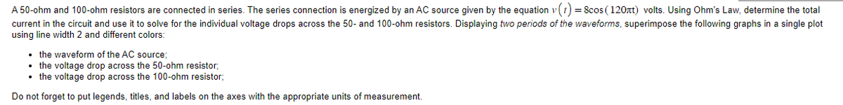
Transcribed Image Text:A 50-ohm and 100-ohm resistors are connected in series. The series connection is energized by an AC source given by the equation v (t) = 8cos (120лt) volts. Using Ohm's Law, determine the total
current in the circuit and use it to solve for the individual voltage drops across the 50- and 100-ohm resistors. Displaying two periods of the waveforms, superimpose the following graphs in a single plot
using line width 2 and different colors:
• the waveform of the AC source;
• the voltage drop across the 50-ohm resistor;
• the voltage drop across the 100-ohm resistor;
Do not forget to put legends, titles, and labels on the axes with the appropriate units of measurement.
Expert Solution
This question has been solved!
Explore an expertly crafted, step-by-step solution for a thorough understanding of key concepts.

Step by step
Solved in 3 steps with 1 images

Knowledge Booster


Learn more about
Need a deep-dive on the concept behind this application? Look no further. Learn more about this topic, electrical-engineering and related others by exploring similar questions and additional content below.Recommended textbooks for you
Power System Analysis and Design (MindTap Course …
Electrical Engineering
ISBN:
9781305632134
Author:
J. Duncan Glover, Thomas Overbye, Mulukutla S. Sarma
Publisher:
Cengage Learning
Power System Analysis and Design (MindTap Course …
Electrical Engineering
ISBN:
9781305632134
Author:
J. Duncan Glover, Thomas Overbye, Mulukutla S. Sarma
Publisher:
Cengage Learning