A 60° strain rosette is installed on the traction-free surface of a component with one of the strain gages aligned along the y-axis, as illustrated in Figure Q2. The gages show the following strain readings upon loading the structure: 6, = 925 x10* ; &, = 740 ×10“ ; &, = -555 x10“ (a) Determine the strains in the x-y directions and show the corresponding strain element. (b) Calculate the principal in-plane strains and the corresponding principal directions. Show the principal strain element. (c) Calculate the in-plane maximum shear strain and show the corresponding strain element.
A 60° strain rosette is installed on the traction-free surface of a component with one of the strain gages aligned along the y-axis, as illustrated in Figure Q2. The gages show the following strain readings upon loading the structure: 6, = 925 x10* ; &, = 740 ×10“ ; &, = -555 x10“ (a) Determine the strains in the x-y directions and show the corresponding strain element. (b) Calculate the principal in-plane strains and the corresponding principal directions. Show the principal strain element. (c) Calculate the in-plane maximum shear strain and show the corresponding strain element.

Mechanics of Materials (MindTap Course List)
9th Edition
ISBN:9781337093347
Author:Barry J. Goodno, James M. Gere
Publisher:Barry J. Goodno, James M. Gere
Chapter7: Analysis Of Stress And Strain
Section: Chapter Questions
Problem 7.7.7P: A thin square plate in biaxial stress is subjected to stresses ?? and ??., as shown in part a of the...

Related questions
Question
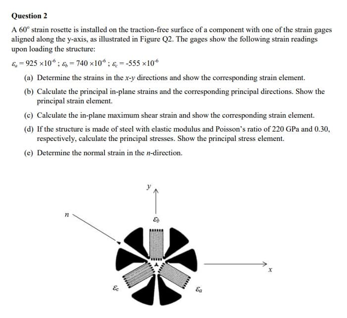
Transcribed Image Text:Question 2
A 60° strain rosette is installed on the traction-free surface of a component with one of the strain gages
aligned along the y-axis, as illustrated in Figure Q2. The gages show the following strain readings
upon loading the structure:
E, = 925 x10“ ; &, = 740 x10“ ; ɛ. = -555 ×106
(a) Determine the strains in the x-y directions and show the corresponding strain element.
(b) Calculate the principal in-plane strains and the corresponding principal directions. Show the
principal strain element.
(c) Calculate the in-plane maximum shear strain and show the corresponding strain element.
(d) If the structure is made of steel with elastic modulus and Poisson's ratio of 220 GPa and 0.30,
respectively, calculate the principal stresses. Show the principal stress element.
(e) Determine the normal strain in the n-direction.
&
Ea
Expert Solution
This question has been solved!
Explore an expertly crafted, step-by-step solution for a thorough understanding of key concepts.

Step by step
Solved in 3 steps with 8 images

Knowledge Booster


Learn more about
Need a deep-dive on the concept behind this application? Look no further. Learn more about this topic, mechanical-engineering and related others by exploring similar questions and additional content below.Recommended textbooks for you
Mechanics of Materials (MindTap Course List)
Mechanical Engineering
ISBN:
9781337093347
Author:
Barry J. Goodno, James M. Gere
Publisher:
Cengage Learning
Mechanics of Materials (MindTap Course List)
Mechanical Engineering
ISBN:
9781337093347
Author:
Barry J. Goodno, James M. Gere
Publisher:
Cengage Learning