a- amplifier? b- What is the configuration of this [ Draw the DC equivalent circuit for the amplifier [ Vi +1 Rin CCI ! VDD = 18 V W www R₁ R₂ Rs www www +₁ RD HH Cc2 RL


Q: Q1. For the scheme shown in figure Q1, using the message signals spectra shown a) Draw the spectrum…
A: All the frequency are written in kHz. Now adding M1'(f) and M2'(f), we get, cos220,000 πt=1+cos…
Q: Suppose you have the following circuit. The switch has been open for a long time, and is closed at…
A:
Q: Match the following Instruments given in column 1 with respective quantities they read in column…
A: Given table,
Q: Determine the Laplace Transform of the signal shown below. Only one cycle is shown but the signal is…
A: Given that A graph of the function f(t) is shown for one cycle period. F(t) is periodic. The graph…
Q: 3. Find the equivalent resistance for the circuit below. T1- R1 68k R4 120 ww R5 15k R3 2.2K -T2 560
A: Given data, Given circuit diagram is,
Q: Solve completely the given circuit below by applying two ac theorems discussed. Choose among…
A: It is given that: Z1=4-j8 ΩZ2=9-j12 ΩZ3=8-j10 ΩZ4=6+j12 ΩV2=30∠-60° V
Q: QUESTION 4 Problem zb: The AC EMF in this electric circuit is described by the following equation: ε…
A: Given: Circuit diagram: E=40ei20t
Q: Consider a continuous-time signal like the given picture with a frequency of 100 Hz. cos(x) V f. a.…
A: According to the question, for the given cosine signal as shown below We need to find (a) The…
Q: -5. Determine the nominal resistance and range of the resistor.
A:
Q: P2.15: A line charge with charge density 2.00 nC/m exists at y = -2.00 m, x = 0.00. (a) A charge Q =…
A:
Q: A CS amplifier utilizes a nMOSFET with μnCox = 400 µA/V², and W/L=10. It is biased at ID= 320 μA and…
A: In a CS amplifier made from MOSFET, has a common source or the source is grounded. This works as a…
Q: Given the field: D = 20 } [–sin20 ap + sin 2 a Find the total charge lying within the volume 1<p <…
A:
Q: What is the shape of a cell in GSM?
A: The solution is provided in the following section.
Q: Switching, Cords and Cables, Motors, and Related Systems 17.a. What's the maximum-rated ampacity of…
A: Given data, 17.a. What's the maximum-rated ampacity of 10 AWG copper, type STO flexible cord, having…
Q: Sketch the root locus of a unity feedback control system with forward path transfer function is…
A:
Q: the process of error controlling using an FEC encoder and decoder in wireless communication with…
A: the process of error controlling using an FEC encoder and decoder in wireless communication with…
Q: The MOSFET in the following circuit is in which configuration? Vi RD. Select one: a. None b. Common…
A: In this question, We need to choose the correct options The given circuit is MOSFET . We need to…
Q: 17824 bits of data is to be transferred from a station A to station B. Assume a call setup time of…
A: Given data: Total number of bits = 17824 Setup time = 0.01s Total separated hopes = 3 The distance…
Q: (b) Consider the circuit in Figure Q.3(b). The switch has been in position 'a' for a long time…
A: Detailed solution is attached with the notes explaining each condition. Thank you.
Q: The capital investment in an energy conservation project is 15,00,000/- and its useful life is 25…
A:
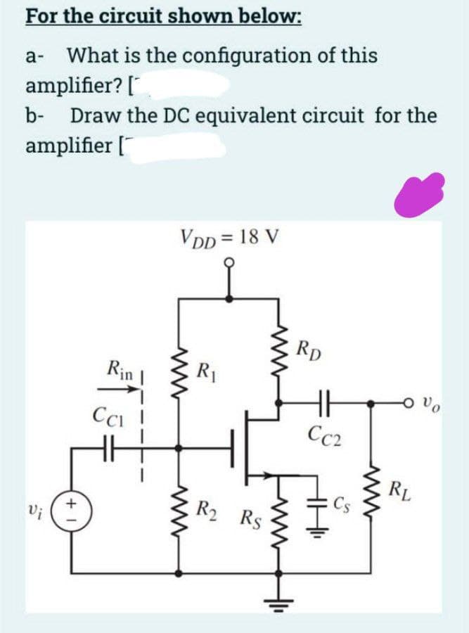
Q: a- What is the configuration of this amplifier? b- Draw the DC equivalent circuit for the amplifier…
A:
Q: Determine the voltages across all capacitors v₁.₂ & v₂ for t> 0. 2 ΚΩ t=0 1mF E 1kΩ + V₂ HH 8 mF - 1…
A:
Q: Define Phase Margin and Gain Margin for continuous and discrete systen
A: Brief idea about phase margin and gain margin
Q: Determine the value of ZL in the circuit of Figure Q3(a) for maximum power transfer.
A:
Q: Sketch the Bode plot of the transfer function. TF = (1 + j0.001ω)/200
A:
Q: (ii) Calculate the maximum efficiency, n for the class B push-pull amplifier shown in Figure Q4(b).…
A: According to the question, for the given class B amplifier as shown below We need to discuss (1)…
Q: A ____________ is used to ensure a known state for a signal. It is typically used with switches to…
A: When external devices are disconnected or have a high impedance, a pull-down resistor is employed to…
Q: A device has an output bit rate of 512 kbits/s. Design a digital modulation scheme for the device if…
A: According to the question, we need to design a digital modulation scheme for which Bit rate=512 k…
Q: 1. What is the wavelength of light waves if their frequency is 5.0X10¹⁴ Hz? a. 0.60 m A b. 6.0 mm c.…
A: 1. Given, Frequency of light, f=5.0×10¹⁴ Hz
Q: QI. Power and Power Factor Correction A factory has the following five major loads: Load 1: A motor…
A:
Q: "A rectangular current loop is lying on the xy-plane defined by 0 <= x <= 1, 0 <= y <=2 (in meters).…
A:
Q: √==G Circuit 1 00 Circuit 2 In the circuits shown in the diagrams above, an uncharged capacitor is…
A:
Q: Some linear system has a transfer function 7(s+3)/(s+4). If the input is 5sin(7t) volts, the ouptput…
A: For any sinusoidal signal, x(t)=Asin(ω0t±θ), passing through a linear system having transfer…
Q: (b) Consider the circuit in Figure Q.2(b). Determine: (i) the value of R that results in a maximum…
A:
Q: Y Figure Q4(b)
A:
Q: In a fish tank, it is possible to have stray potentials from lights and other equipment. The fish in…
A: The equipotential lines for the given dipole are shown below: The orientation of the fish is in a…
Q: difference between short and long transmission line
A:
Q: 11. Which of the following is the drawback for cordless telephones? a) Security b) Wireless…
A: Answer: c) Limited coverage area Explanation: a) It is not a valid option. The wired and wireless…
Q: discuss the application of nyquist criterion to determine stability of a closed loop control system
A: Nyquist criterion: Nyquist criterion is a tool widely used to determine the stability of a system.
Q: Problem 12. A cable has the following primary con- stants: resistance R= 80 22/loop km, conductance,…
A: Given: A cable has the following primary constants Resistance, R=80 Ωloop km Conductance, G=2 μSkm…
Q: ergy-efficient wireless network, which emphasizes energy efficiency ectrum efficiency, have been…
A: In wireless communication systems, the nonlinear effect and inefficiency of power amplifier (PA)…
Q: Discuss the operation of the following control system . (i) Servo Motors (ii) Synchronous
A:
Q: Q.2 (a) Consider the circuit in Figure Q.2(a). Using Nodal analysis, find: (1) P₁. V and Vs. (ii)…
A:
Q: 1. Determine the line currents in the given three-phase circuit. I₂ 44020° 440/120° n a 440-120° (50…
A:
Q: R(s) K S pote 1 1 2s² 4 1 s+1 C(s)
A:
Q: Determine I using Nodal Analysis.
A: The required current I can be obtained by applying kirchhoff's current law to the nodes of the…
Q: Assume that the currents I1, I2, and I are in the directions indicated by the arrows in the figure…
A: Given that Resistors, R1= 5.25 ohm R2= 3.90 ohm R3= 2.70 ohm R4= 1.70 ohm The circuit is shown…
Q: 1. Write the equations at the specified mesh a
A:
Q: for system having open loop transfer function Ofind type of the - K (S+4). S (5+ 55² +65) g a GI(S)…
A: Given

Step by step
Solved in 2 steps with 2 images


- What is the difference between a diode and rectifier?a half-wave rectifier circuit in the figure below has a transformer inserted between the source and the remainder of the circuit. The source is 240 Vrms at 60 Hz, and the load resistor is 20 ohm. (a) Determine the required transformer turns ratio (Ns/Np) so that the average load current is 12 A. (b) Determine the average current in the primary winding of the transformer.A fully controlled three-phase rectifier bridge circuit supplies a dc load of 300V,60A, from 415V 3-phase ac supply via delta-star transformer. (i) Determine the required thyristor and transformer specifications. (ii) Draw the load and thyristor voltages when firing angle alpha = 60°. (ii) If a commutating diode is placed across the load, determine the FWD specification and then calculate the average load voltage and FWD average current when firing angle alpha = 45°
- For a Full wave rectifier circuit, the AC voltage input to transformer primary is 115V. Transformer secondary voltage is 50V. Load resistor is 25 ohms. Determine Peak and Average DC Component of load voltage. (Assume ideal diodes) a.VDC (peak) = 25.4 V; VDC (average) = 18.5V b.VDC (peak) = 35.4 V; VDC (average) = 22.5V c.VDC (peak) = 38.4 V; VDC (average) = 23.5V d.VDC (peak) = 50 V; VDC (average) = 34.5V1. A single-phase, 120V, 50Hz supply is connected to a controlled half-wave thyristor rectifier and series R-L load consisting of a resistor R of 350 ohms and inductor L of 150mH. The thyristor firing angle is 65 degrees. Assume the diode and thyristor are ideal. i) calculate the dc load voltage VDC and the load dc current IDC. ii) briefly explain why a freewheeling diode is often connected in parallel to an R-L connected load in rectifier circuitsCalculate the rms load current for the single phase uncontrolled half-wave rectifier when the source voltage of 200V at a frequency of 50Hz, and load resistance is 10ohm.
- i) Draw the circuit diagram of the single phase full wave controlled rectifier (RL load) with center-tapped transformer and compare its performance with uncontrolled rectifier operation. (ii) A single phase fully controlled bridge rectifier circuit has DC output voltage 175 V for an AC supply voltage of 210 V rms. Find the firing angle delay of the circuit for the following cases (a) Converter mode (b) Inverter modeA single phase full wave controlled bridge rectifier has a source of 800V rms and frequency of 50 Hz. This source is connected to the rectifier through a transformer of 4:1 voltage ratio. Assuming Lis very high and stable output current of 1.8A (a) Determine the value of the triggering angle to get 75% of the maximum power at the output of this rectifier (b) Find the value of R. (c) Specify the * required voltage rating of thyristorsCreate a schematic diagram for building an AC-DC power supply that uses a complete bridge rectifier, filter capacitors, and regulators and has a selectable output voltage. Keep in mind: When a load is attached, the power supply must be able to deliver at least 500mA of output current.
- Answer in Sentence/Paragraph form. Maximum of 5 sentences each. Lesson: Electronics: HALF-WAVE Rectifier with and without Filter1. What is the function of the filters?2. What is TUF or Transformer Utilization factor? 3. What is the average value of output voltage for half-wave rectifier? 4. What is the peak factor?What is the condition to obtain the maximum efficiency of a Rectifier? Neglecting the value of total resistance Neglecting the value of transformer resistance Neglecting the value of diode resistance Neglecting the value of load resistanceIn the circuit in the figure, an AC voltmeter will be made with full wave rectifier circuit structure. R = 50ohm and diodesResistance values in the direction of transmission are Rd = 100ohm. Inside of the DC ammeter to be used as indicatorthe resistance is very, very small. The AC mark to be measured is Vs = 100 Sinwt Volts.a- Draw the shape of the current passing through the DC Ammeter and calculate its maximum value.b- Find the average value of the current passing through the DC Ammeter.c- Analyze the voltage seen at the ends of diode D1 for both alternans.d- Find the Rms value of the voltage seen at the ends of the diode D1.