(a) An instrumentation amplifier shown in Figure 1 is an anplifier of low-level signals used in process control or measurement applications and conmercially available in single-package units: (i) Show that vb=R3/R2(1+2R1/Rg)(v2−v1). (ii) Assume R1=50kΩ and R2=R3. If Rg is a tunable resistor with resistance ranging from 1000ohms to 10k ohms, what is the range of variable gain? (iii) Assume R1=10kΩ and R2=R3,∣v2−v1∣≤120mV and Vcc=12 V. In order to keep the op-amp circuit work in linear region, what is the minimum value of Ry ? (iv) State TWO characteristics of this op-amp circuit.
(a) An instrumentation amplifier shown in Figure 1 is an anplifier of low-level signals used in process control or measurement applications and conmercially available in single-package units: (i) Show that vb=R3/R2(1+2R1/Rg)(v2−v1). (ii) Assume R1=50kΩ and R2=R3. If Rg is a tunable resistor with resistance ranging from 1000ohms to 10k ohms, what is the range of variable gain? (iii) Assume R1=10kΩ and R2=R3,∣v2−v1∣≤120mV and Vcc=12 V. In order to keep the op-amp circuit work in linear region, what is the minimum value of Ry ? (iv) State TWO characteristics of this op-amp circuit.

Introductory Circuit Analysis (13th Edition)
13th Edition
ISBN:9780133923605
Author:Robert L. Boylestad
Publisher:Robert L. Boylestad
Chapter1: Introduction
Section: Chapter Questions
Problem 1P: Visit your local library (at school or home) and describe the extent to which it provides literature...

Related questions
Question
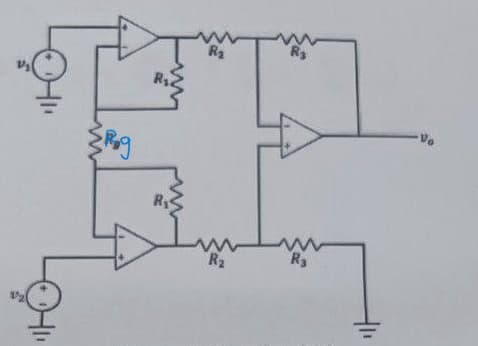
(a) An instrumentation amplifier shown in Figure 1 is an anplifier of low-level signals used in process control or measurement applications and conmercially available in single-package units:
(i) Show that vb=R3/R2(1+2R1/Rg)(v2−v1).
(ii) Assume R1=50kΩ and R2=R3. If Rg is a tunable resistor with resistance ranging from 1000ohms to 10k ohms, what is the range of variable gain?
(iii) Assume R1=10kΩ and R2=R3,∣v2−v1∣≤120mV and Vcc=12 V. In order to keep the op-amp circuit work in linear region, what is the minimum value of Ry ?
(iv) State TWO characteristics of this op-amp circuit.
Transcribed Image Text:{Rog
R₂
R₂
R₂
Expert Solution
This question has been solved!
Explore an expertly crafted, step-by-step solution for a thorough understanding of key concepts.

Step by step
Solved in 10 steps with 7 images

Knowledge Booster


Learn more about
Need a deep-dive on the concept behind this application? Look no further. Learn more about this topic, electrical-engineering and related others by exploring similar questions and additional content below.Recommended textbooks for you
Introductory Circuit Analysis (13th Edition)
Electrical Engineering
ISBN:
9780133923605
Author:
Robert L. Boylestad
Publisher:
PEARSON

Delmar's Standard Textbook Of Electricity
Electrical Engineering
ISBN:
9781337900348
Author:
Stephen L. Herman
Publisher:
Cengage Learning

Programmable Logic Controllers
Electrical Engineering
ISBN:
9780073373843
Author:
Frank D. Petruzella
Publisher:
McGraw-Hill Education
Introductory Circuit Analysis (13th Edition)
Electrical Engineering
ISBN:
9780133923605
Author:
Robert L. Boylestad
Publisher:
PEARSON
Delmar's Standard Textbook Of Electricity
Electrical Engineering
ISBN:
9781337900348
Author:
Stephen L. Herman
Publisher:
Cengage Learning
Programmable Logic Controllers
Electrical Engineering
ISBN:
9780073373843
Author:
Frank D. Petruzella
Publisher:
McGraw-Hill Education

Fundamentals of Electric Circuits
Electrical Engineering
ISBN:
9780078028229
Author:
Charles K Alexander, Matthew Sadiku
Publisher:
McGraw-Hill Education

Electric Circuits. (11th Edition)
Electrical Engineering
ISBN:
9780134746968
Author:
James W. Nilsson, Susan Riedel
Publisher:
PEARSON

Engineering Electromagnetics
Electrical Engineering
ISBN:
9780078028151
Author:
Hayt, William H. (william Hart), Jr, BUCK, John A.
Publisher:
Mcgraw-hill Education,