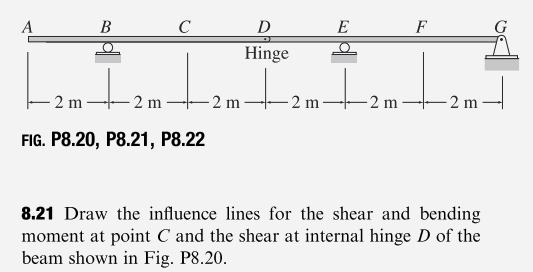
A B C D E F Hinge 2 m 2 m 2 m -2 m 2 m. 2 m FIG. P8.20, P8.21, P8.22 8.21 Draw the influence lines for the shear and bending moment at point C and the shear at internal hinge D of the beam shown in Fig. P8.20.
Q: 5.3 The beam is subjected to a load F = 400 N and is supported by the rope and the smooth surfaces…
A: The load F is 400 N.We need to draw FBD and than calculate reaction at A and B
Q: Part A The magnitude of the force exerted on the wrench is 20 lb (Figure 1). What moment does the…
A: The magnitude of force is 20 lb
Q: F2-7. Determine the horizontal and vertical components of reaction at the pins A, B, and D of the…
A: Step 1:Step 2:Step 3:
Q: The following steel shaft (1) is rigidly connected at B to another aluminum shaft (2). Both shafts…
A: Step 1:Step 2: Step 3: Step 4:
Q: Station Line Length (Ft) Interior Angles A 89°30'30" AB 447.60 B 89°30'30" BC 180.00 C 89°45'45" CD…
A:
Q: Water travels through a circular pipe with a diameter of 400 mm and at a speed of 5 m/s. The…
A: The inertial force created by the flow of water in the pipe is 3142.5 N.Explanation:The options…
Q: Situation A: A beam is attached to a wire on the one end and is rested to an inclined plane on the…
A: Absolutely, here's a brief answer to the beam situation neglecting friction (questions 17 &…
Q: 3. The following hollow square section (wall thickness 1") is subjected to an unsymmetric bending…
A:
Q: A 5inch diameter steel sphere is rigidly attached to the end of a 24-in.-long, 1(1)/(2)inch diameter…
A: Step 1: Step 2:Step 3:Step 4:
Q: A 1.5-ft³rigid tank contains saturated refrigerant-134 at 170 psia. Initially, 20 percent of the…
A:
Q: 0.4 m B T 2 kN·m/m 0.6 m,
A:
Q: CHAPTER TH 3.25 The resultant of the three concurrent forces shown is 100 lb and has an angle of…
A:
Q: 3. The power P dissipated in a resistor is given by P = . If E=200 volts and R = 8 ohms, find the…
A:
Q: 3. The tow truck’s front wheel will be lifted off the ground if the moment of the load W about the…
A: The largest weight carried by the tow truck is 6020lbExplanation:Step 1:Weight of the truck is…
Q: Solve problem 4.33.
A: Detailed step by step solution is given below, still if you have any query please feel free to…
Q: It is required to lay out a line on the ground 500 m. long. The 50 m tape used was 0.015 m longer at…
A:
Q: A large grain elevator is located 40 feet from the centerline of a two-lane highway (55 mph…
A: Step 1:Step 2:
Q: Accurate solution?
A: The beam can be illustrated as: To get the reactions:…
Q: The 1.9-Mg car increases its speed uniformly from rest to 17 m/s in 28 s up the inclined road. Part…
A:
Q: Suppose we have a uniform beam that is 3.40metres long has a flexural rigidity of 31915N Find the…
A:
Q: 3.16 Three forces of 900 lb, 1000 lb, and 600 lb are acting on a boat. The first force acts due…
A: Note: Dear student as per our company guidelines i am solving first problem only (i.e problem 3.16…
Q: Example 1 A sand come test has been performed in a competed fill made with the soil described in 21…
A: Please refer below pages.If you have any doubts please feel free to ask.Explanation:Step 1:…
Q: Force Systems 3.23 and 3.24 Determine the resultant force for each of the co- planar concurrent…
A: All parts are solved below.Explanation:
Q: Using the Rational Method, determine the 10-yr peak flow at a stormwater inlet in Tallahassee,…
A: Average intensity of 10 year (i) = 5.6 in./hr Determine the 10 year peak flow at stormwater inlet…
Q: In using the bolt cutter shown, a worker applies two forces to the handles. Determine the magnitude…
A: Step 1:Given data :P=360 N Step 2:∑Fx=0;Bx=0∑MA=096*By-24*F=0F=4By ...(1)Step…
Q: just simple answer thanks.
A: Step 1: Step 2: Step 3: Step 4:
Q: F₁ F2 Ф A L1 B N C L3 D h y F3 Find the equivalent resultant force and couple moment of the force…
A:
Q: For the house layout below, if the height of the basement ceiling is 8 feet, and the stairway design…
A:
Q: HREE Resultants of Coplanar F Section 3.3 Moment of a F 5.29 The four forces shown have paral AB is…
A:
Q: of gas in the process of This image shows the a) Production; CO2; photosynthesis b) Consumption;…
A: The image you sent is a graph on a piece of white paper. It shows levels of oxygen (O2) and carbon…
Q: door of a submarine is 88 feet deep in the sea. Determine the force (lb) to which it is subjected if…
A:
Q: A 16-foot-long single overhang beam is loaded as shown. Assuming a determine the maximum bending…
A: The given question was incomplete, so I assume the allowable design is "3000 psi." Therefore, the…
Q: You are requested to perform the following calculations by hand. Determine the shear and moment…
A: Step 1: Given data.Step 2: Determination for reactions at support.Step 3: Calculation for Shear…
Q: 5. Three ropes were tied to an eyebolt as shown below. The magnitude of the ropes applied to the…
A: FR =164.49 direction of resultant is 70.37o with positive x- axis.Explanation:Approach to solving…
Q: 2. A timber beam is used to support two concentrated loads and a distributed load over its…
A:
Q: what must be the (a)x and (b)y coordinates of particle 3.
A:
Q: can this question be solved using the Slope Deflection Method
A:
Q: Given Beam with FBD for Reactions 50 kN 2m 3m Solution for solving reactions 20 kN/m 5m Draw the…
A: *I assigned letters A,B,C,D to the beam for easier reference points *Formula of Area Moment Diagram…
Q: a v-shaped channel, build of unplanned timber 0.080 m/ with a velocity of 2.5 m/s. each of the sides…
A:
Q: A large grain elevator is located 40 feet from the centerline of a two-lane highway (55 mph speed…
A:
Q: 12.2 A 20 m long concrete pile is shown in Figure P12.2. Estimate the ultimate point load Q, by a.…
A: Required: Ultimate Point Load, Qp a. Meyerhof's Method b. Vesic's Method (m=600) c. Coyle and…
Q: Find the required spacing for two-leg, single loop #3 stirrups in the beam below. Determine a…
A: Detailed solution is provided belowPlease read carefullyAsk me if you have any doubtsThank you.…
Q: Calculate the support reactions. 4m 2 kN/m 2m 10 kN ↓ 10 B
A:
Q: 3. Derive equations of motion for the two mass system. Mass m₁ sits on a circular track and rides on…
A: Step 1: Step 2:For any query feel free to drop comments. Step 3: Step 4:
Q: B D89°30'30" 184.90' C Angele D Bearing 0° East 488.60' West+ North st +1 South A 89°45'45" 180°0'0"…
A:
Q: H.W-4. A ball is thrown from A. If it is required to clear the wall at B, determine the minimum…
A: Approach to solving the question: Detailed explanation: Examples: Key references:
Q: 6-49 A beam has the cross section shown. If it is made of steel that has an allowable stress of…
A:
Q: Find the upgrade and downgrade service flow rates and service volumes for an eight lane freeway with…
A: The objective of the question is to calculate the service flow rates and service volumes for an…
Q: 11. A, B, C are vectors defined by A = 8i + 2j- 3k, B = 3i-6j+ 4k, and C=2i-2j-k, where i, j, k are…
A: Step 1:Step 2:Step 3:
Q: DESIGN A PILE CAP USING THE STRUT AND MODELING METHOD. A 16"x16" precast concrete pile with pile…
A: Given- size of pile - pile capacity- 122 kips Fc- 5000 psi Length of…
Draw influence lines for this figure below
Step by step
Solved in 2 steps with 1 images
- Draw the influence lines for the vertical reactions at supports A and C, the shear at just to the right of A, and the bending moment at point B of the beam shown in Fig. P8.9.Draw the influence lines for the shear and bending moment at point D of the beam shown in Fig. P8.23.Draw the influence lines for the shear and bending moment at point B of the beam shown in Fig. P8.24.
- Draw the influence lines for the vertical reaction and the reaction moment at support A and the shear and bending moment at point B of the cantilever beam shown in Fig. P8.5.Draw the influence lines for the shear and bending moment at point B and the shears just to the left and just to the right of support C of the beam shown in Fig. P8.12Draw the influence lines for the shear and bending moment at point C and the shear at internal hinge D of the beam shown in Fig. P8.20.
- Draw the influence lines for the shears and bending moments at points B and E of the beam shown in Fig. P8.31Draw the influence lines for the vertical reactions at supports A and B and the shear and bending moment at point D of the frame shown in Fig. P8.17.Draw the influence lines for the vertical reaction and reaction moment at support A and the shear and bending moment at point C of the frame shown in Fig. P8.18.