B D Hinge E F -12 ft--12 ft-+12 ft- -12 ft-H12 ft- -12 ft FIG. P8.20, P8.21, P8.22
B D Hinge E F -12 ft--12 ft-+12 ft- -12 ft-H12 ft- -12 ft FIG. P8.20, P8.21, P8.22

Chapter8: Influence Lines
Section: Chapter Questions
Problem 25P

Related questions

Question
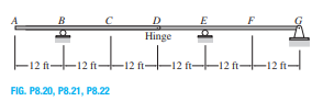
Draw the influence lines for the shear and bending moment at point C and the shear at internal hinge D of the beam shown in Fig. P8.20.
Transcribed Image Text:B
D
Hinge
E
F
-12 ft--12 ft-+12 ft-
-12 ft-H12 ft-
-12 ft
FIG. P8.20, P8.21, P8.22
Expert Solution
This question has been solved!
Explore an expertly crafted, step-by-step solution for a thorough understanding of key concepts.

Step by step
Solved in 7 steps with 9 images

Knowledge Booster


Learn more about
Need a deep-dive on the concept behind this application? Look no further. Learn more about this topic, civil-engineering and related others by exploring similar questions and additional content below.Recommended textbooks for you