A balanced Y-connected source is connected to a A-connected balanced load. The phase voltage of the source is 110 Vrms with the phase a as reference, assume the phase sequence is ABC. Impedance of the transmission line between source and load is 10+j5 each branch. If the current source at phase-a is 1.264-66° A, (i) Draw the three phase Y-Y connected equivalent circuit. (ii) Calculate the resistor and reactance of the load each branch. (iii) Calculate the line to line voltage of the load.
A balanced Y-connected source is connected to a A-connected balanced load. The phase voltage of the source is 110 Vrms with the phase a as reference, assume the phase sequence is ABC. Impedance of the transmission line between source and load is 10+j5 each branch. If the current source at phase-a is 1.264-66° A, (i) Draw the three phase Y-Y connected equivalent circuit. (ii) Calculate the resistor and reactance of the load each branch. (iii) Calculate the line to line voltage of the load.

Introductory Circuit Analysis (13th Edition)
13th Edition
ISBN:9780133923605
Author:Robert L. Boylestad
Publisher:Robert L. Boylestad
Chapter1: Introduction
Section: Chapter Questions
Problem 1P: Visit your local library (at school or home) and describe the extent to which it provides literature...

Related questions

Concept explainers
Three-Phase Transformers
Three-segment transformers are a type of transformer used to transform voltages of electrical systems into three ranges. Two type transformers are shell-type transformer and core type transformer. In brief, it could be described because of the exquisite kinds of configurations.
Transformer
Ever since electricity has been created, people have started using it in its entirety. We see many types of Transformers in the neighborhoods. Some are smaller in size and some are very large. They are used according to their requirements. Many of us have seen the electrical transformer but they do not know what work they are engaged in.
Question
power system
please answer
Transcribed Image Text:(c)
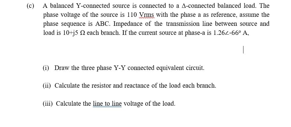
A balanced Y-connected source is connected to a A-connected balanced load. The
phase voltage of the source is 110 Vrms with the phase a as reference, assume the
phase sequence is ABC. Impedance of the transmission line between source and
load is 10+j5 2 each branch. If the current source at phase-a is 1.264-66° A,
(i) Draw the three phase Y-Y connected equivalent circuit.
(ii) Calculate the resistor and reactance of the load each branch.
(iii) Calculate the line to line voltage of the load.
Expert Solution
This question has been solved!
Explore an expertly crafted, step-by-step solution for a thorough understanding of key concepts.

Step by step
Solved in 2 steps with 2 images

Knowledge Booster


Learn more about
Need a deep-dive on the concept behind this application? Look no further. Learn more about this topic, electrical-engineering and related others by exploring similar questions and additional content below.Recommended textbooks for you
Introductory Circuit Analysis (13th Edition)
Electrical Engineering
ISBN:
9780133923605
Author:
Robert L. Boylestad
Publisher:
PEARSON

Delmar's Standard Textbook Of Electricity
Electrical Engineering
ISBN:
9781337900348
Author:
Stephen L. Herman
Publisher:
Cengage Learning

Programmable Logic Controllers
Electrical Engineering
ISBN:
9780073373843
Author:
Frank D. Petruzella
Publisher:
McGraw-Hill Education
Introductory Circuit Analysis (13th Edition)
Electrical Engineering
ISBN:
9780133923605
Author:
Robert L. Boylestad
Publisher:
PEARSON
Delmar's Standard Textbook Of Electricity
Electrical Engineering
ISBN:
9781337900348
Author:
Stephen L. Herman
Publisher:
Cengage Learning
Programmable Logic Controllers
Electrical Engineering
ISBN:
9780073373843
Author:
Frank D. Petruzella
Publisher:
McGraw-Hill Education

Fundamentals of Electric Circuits
Electrical Engineering
ISBN:
9780078028229
Author:
Charles K Alexander, Matthew Sadiku
Publisher:
McGraw-Hill Education

Electric Circuits. (11th Edition)
Electrical Engineering
ISBN:
9780134746968
Author:
James W. Nilsson, Susan Riedel
Publisher:
PEARSON

Engineering Electromagnetics
Electrical Engineering
ISBN:
9780078028151
Author:
Hayt, William H. (william Hart), Jr, BUCK, John A.
Publisher:
Mcgraw-hill Education,