(a) Calculate the required section modulus S if Oallow = 18,000 psi, L = 32 ft, P = 2900 lb, and q = 450 lb/ft. Then select a suitable I-beam (S shape) from Table F-2(a), Appendix F, and recalculate S taking into account the weight of the beam. Select a new beam size if necessary. (b) What is the maximum load P that can be applied to your final beam selection in part (a)?
(a) Calculate the required section modulus S if Oallow = 18,000 psi, L = 32 ft, P = 2900 lb, and q = 450 lb/ft. Then select a suitable I-beam (S shape) from Table F-2(a), Appendix F, and recalculate S taking into account the weight of the beam. Select a new beam size if necessary. (b) What is the maximum load P that can be applied to your final beam selection in part (a)?

Mechanics of Materials (MindTap Course List)
9th Edition
ISBN:9781337093347
Author:Barry J. Goodno, James M. Gere
Publisher:Barry J. Goodno, James M. Gere
Chapter5: Stresses In Beams (basic Topics)
Section: Chapter Questions
Problem 5.6.7P: A simple beam AB is loaded as shown in the figure. Calculate the required section modulus S if ^aibw...

Related questions
Question
100%
Transcribed Image Text:2
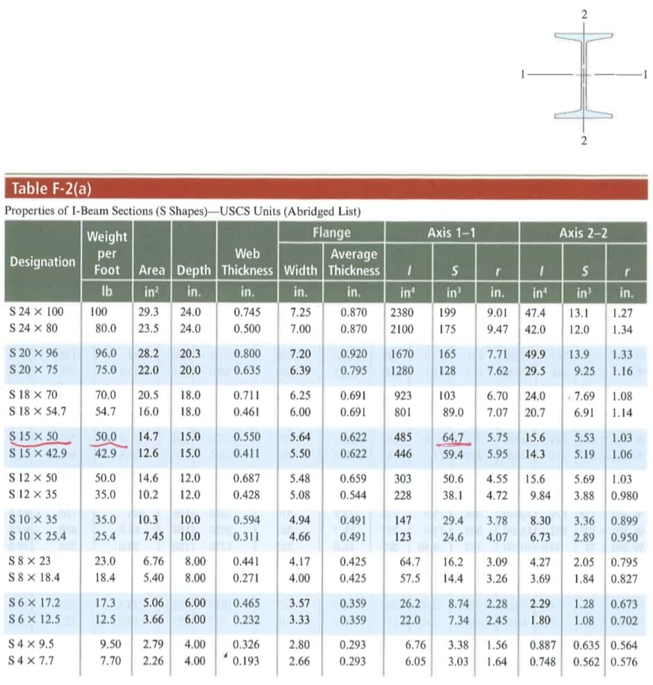
Table F-2(a)
Properties of I-Beam Sections (S Shapes)-USCS Units (Abridged List)
Weight
Flange
Axis 1-1
Axis 2-2
Web
per
Foot
Average
Area Depth Thickness Width Thickness
Designation
Ib
in?
in.
in.
in.
in.
in
in
in.
in
in
in.
S 24 X 100
S 24 X 80
100
29.3
24.0
0.745
7.25
0.870
2380
199
9.01
47.4
13.1
1.27
80.0
23.5
24.0
0.500
7.00
0.870
2100
175
9.47
42.0
12.0
1.34
S 20 x 96
S 20 x 75
96.0
1670
1280
28.2
20.3
0.800
7.20
0.920
165
7.71
49.9
13.9
1.33
75.0
22.0
20.0
0.635
6.39
0.795
128
7.62
29.5
9.25
1.16
S 18 X 70
S 18 X 54.7
70.0
20.5
18.0
0.711
6.25
0.691
923
103
6.70
24.0
7.69
1.08
54.7
16.0
18.0
0.461
6.00
0.691
801
89.0
7.07
20.7
6.91
1.14
S 15 x 50
S 15 x 42.9
50.0
14.7
15.0
0.550
5.64
0.622
485
64.7
5.75
15.6
5.53
1.03
42.9
12.6
15.0
0.411
5.50
0.622
446
59.4
5.95
14.3
5.19
1.06
S 12 x 50
S 12 x 35
50.0
14.6
12.0
0.687
5.48
0.659
303
50.6
4.55
15.6
5.69
1.03
35.0
10.2
12.0
0.428
5.08
0.544
228
38.1
4.72
9.84
3.88
0.980
S 10 x 35
S 10 x 25.4
35.0
10.3
10.0
0.594
4.94
0.491
147
29.4
3.78
8.30
3.36
0.899
25.4
7.45
10.0
0.311
4.66
0.491
123
24.6
4.07
6.73
2.89
0.950
S 8 X 23
S8 X 18.4
23.0
6.76
8.00
0.441
4.17
0.425
64.7
16.2
3.09
4.27
2.05
0.795
18.4
5.40
8.00
0.271
4.00
0.425
57.5
14.4
3.26
3.69
1.84
0.827
S6x 17.2
17.3
5.06
6.00
0.465
3.57
0.359
26.2
8.74
2.28
2.29
1.28
0.673
S6x 12.5
12.5
3.66
6.00
0.232
3.33
0.359
22.0
7.34
2.45
1.80
1.08
0.702
S4 x 9.5
S4 x 7.7
9.50
2.79
4.00
0.326
2.80
0.293
6.76
3.38
1.56
0.887
0.635 0.564
7.70
2.26
4.00
0.193
2.66
0.293
6.05
3.03
1.64
0.748
0.562 0.576
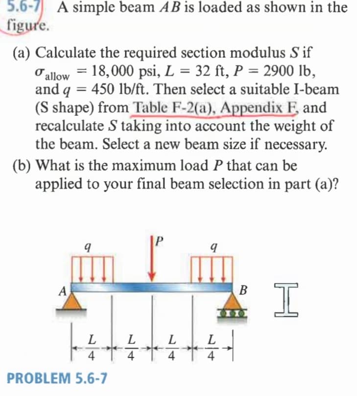
Transcribed Image Text:5.6-7 A simple beam AB is loaded as shown in the
figure.
(a) Calculate the required section modulus S if
Oallow = 18,000 psi, L = 32 ft, P = 2900 lb,
and q = 450 lb/ft. Then select a suitable I-beam
(S shape) from Table F-2(a), Appendix F and
recalculate S taking into account the weight of
the beam. Select a new beam size if necessary.
%3D
%3D
(b) What is the maximum load P that can be
applied to your final beam selection in part (a)?
A
L
L
L
4
4
4
4
PROBLEM 5.6-7
Expert Solution
This question has been solved!
Explore an expertly crafted, step-by-step solution for a thorough understanding of key concepts.

Step by step
Solved in 4 steps with 3 images

Knowledge Booster


Learn more about
Need a deep-dive on the concept behind this application? Look no further. Learn more about this topic, mechanical-engineering and related others by exploring similar questions and additional content below.Recommended textbooks for you
Mechanics of Materials (MindTap Course List)
Mechanical Engineering
ISBN:
9781337093347
Author:
Barry J. Goodno, James M. Gere
Publisher:
Cengage Learning
Mechanics of Materials (MindTap Course List)
Mechanical Engineering
ISBN:
9781337093347
Author:
Barry J. Goodno, James M. Gere
Publisher:
Cengage Learning