
Mechanics of Materials (MindTap Course List)
9th Edition
ISBN: 9781337093347
Author: Barry J. Goodno, James M. Gere
Publisher: Cengage Learning
expand_more
expand_more
format_list_bulleted
Videos
Textbook Question
Chapter 5, Problem 5.6.6P
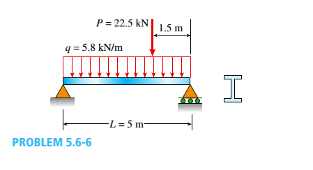
A simple beam of length L = 5 m carries a uniform load of intensity q = 5,8 kN/m and a concentrated load 22.5 kN (see figure).
(a) Assuming tra]]ow = 110 MPa, calculate the required section modulus S. Then select the most economical wide-flange beam (W shape) from Table F-l(b) in Appendix F, and recalculate S, taking into account the weight of the beam. Select a new beam if necessary.
(b) Repeat part (a), but now assume that the design requires that the W shape must be used in weak axis bending (i.e., it must bend about the 2-2 (or y) axis of the cross section).
Expert Solution & Answer

Trending nowThis is a popular solution!

Chapter 5 Solutions
Mechanics of Materials (MindTap Course List)
Ch. 5 - A steel wire with a diameter of d = 1/16 in. is...Ch. 5 - A copper wire having a diameter ofd = 4 mm is bent...Ch. 5 - A 4.75-in, outside diameter polyethylene pipe...Ch. 5 - A cantilever beam AB is loaded by a couple M0at...Ch. 5 - A thin strip of steel with a length of L =19 in....Ch. 5 - A bar of rectangular cross section is loaded and...Ch. 5 - A simply supported beam with a length L = 10 ft...Ch. 5 - A cantilever beam is subjected to a concentrated...Ch. 5 - A thin strip of hard copper (E = 16,000 ksi)...Ch. 5 - A steel wire (E = 200 GPa) of a diameter d = L25...
Ch. 5 - A thin, high-strength steel rule (E = 30 x 10ft...Ch. 5 - A simply supported wood beam AB with a span length...Ch. 5 - Beam ABC has simple supports at A and B and an...Ch. 5 - A simply supported beam is subjected to a in early...Ch. 5 - Each girder of the lift bridge (sec figure) is 180...Ch. 5 - A freight-car axle AS is loaded approximately as...Ch. 5 - A seesaw weighing 3 lb/ft of length is occupied by...Ch. 5 - During construction of a highway bridge, the main...Ch. 5 - The horizontal beam ABC of an oil-well pump has...Ch. 5 - A railroad tie (or sleeper) is subjected to two...Ch. 5 - A fiberglass pipe is lifted by a sling, as shown...Ch. 5 - A small dam of height h = 2.0 m is constructed of...Ch. 5 - Determine the maximum tensile stress (7, (due to...Ch. 5 - Determine the maximum bending stress emaxdue to...Ch. 5 - A simple beam A B of a span length L = 24 ft is...Ch. 5 - Determine the maximum tensile stress erand maximum...Ch. 5 - A cantilever beam A3, loaded by a uniform load and...Ch. 5 - A canti lever beam A B of a n isosceles t...Ch. 5 - A cantilever beam, a C12 x 30 section, is...Ch. 5 - A frame ABC travels horizontally with an...Ch. 5 - A beam ABC with an overhang from B to C supports a...Ch. 5 - A cantilever beam AB with a rectangular cross...Ch. 5 - A beam with a T-section is supported and loaded as...Ch. 5 - Consider the compound beam with segments AB and...Ch. 5 - A small dam of a height h = 6 ft is constructed of...Ch. 5 - A foot bridge on a hiking trail is constructed...Ch. 5 - A steel post (E=30×106) having thickness t = 1/8...Ch. 5 - Beam ABCDE has a moment release just right of...Ch. 5 - A simply supported wood beam having a span length...Ch. 5 - A simply supported beam (L = 4.5 m) must support...Ch. 5 - The cross section of a narrow-gage railway bridge...Ch. 5 - A fiberglass bracket A BCD with a solid circular...Ch. 5 - A cantilever beanie B is loaded by a uniform load...Ch. 5 - A simple beam of length L = 5 m carries a uniform...Ch. 5 - A simple beam AB is loaded as shown in the figure....Ch. 5 - A pontoon bridge (see figure) is constructed of...Ch. 5 - A floor system in a small building consists of...Ch. 5 - The wood joists supporting a plank Floor (see...Ch. 5 - A beam ABC with an overhang from B to C is...Ch. 5 - -12 A "trapeze bar" in a hospital room provides a...Ch. 5 - A two-axle carriage that is part of an over head...Ch. 5 - A cantilever beam AB with a circular cross section...Ch. 5 - A propped cantilever beam A BC (see figure) has a...Ch. 5 - A small balcony constructed of wood is supported...Ch. 5 - A beam having a cross section in the form of an un...Ch. 5 - A beam having a cross section in the form of a...Ch. 5 - Determine the ratios of the weights of four beams...Ch. 5 - Prob. 5.6.20PCh. 5 - A steel plate (called a cover ploie) having...Ch. 5 - A steel beam ABC is simply supported at A and...Ch. 5 - A retaining wall 6 ft high is constructed of...Ch. 5 - A retaining wall (Fig. a) is constructed using...Ch. 5 - A beam of square cross section (a = length of each...Ch. 5 - The cross section of a rectangular beam having a...Ch. 5 - A tapered cantilever beam A B of length L has...Ch. 5 - .2 A ligmio.irc ii supported by two vorlical beams...Ch. 5 - Prob. 5.7.3PCh. 5 - Prob. 5.7.4PCh. 5 - Prob. 5.7.5PCh. 5 - A cantilever beam AB with rectangular cross...Ch. 5 - A simple beam ABC having rectangular cross...Ch. 5 - A cantilever beam AB having rectangular cross...Ch. 5 - The shear stresses t in a rectangular beam arc...Ch. 5 - .2 Calculate the maximum shear stress tmaxand the...Ch. 5 - A simply supported wood beam is subjected to...Ch. 5 - A simply supported wood beam with overhang is...Ch. 5 - Two wood beams, each of rectangular cross section...Ch. 5 - A cantilever beam of length L = 2 m supports a...Ch. 5 - A steel beam of length L = 16 in. and...Ch. 5 - A beam of rectangular cross section (width/) and...Ch. 5 - A laminated wood beam on simple supports (figure...Ch. 5 - A laminated plastic beam of square cross section...Ch. 5 - A wood beam AB on simple supports with span length...Ch. 5 - A simply supported wood beam of rectangular cross...Ch. 5 - A square wood platform is 8 ft × 8 ft in area and...Ch. 5 - A wood beam ABC with simple supports at A and B...Ch. 5 - A wood pole with a solid circular cross section (d...Ch. 5 - A simple log bridge in a remote area consists of...Ch. 5 - A vertical pole consisting of a circular tube of...Ch. 5 - A circular pole is subjected to linearly varying...Ch. 5 - A sign for an automobile service station is...Ch. 5 - A steel pipe is subjected to a quadratic...Ch. 5 - -1 through 5.10-6 A wide-flange beam (see figure)...Ch. 5 - -1 through 5.10-6 A wide-flange beam (see figure)...Ch. 5 - -1 through 5.10-6 A wide-flange beam (see figure)...Ch. 5 - -1 through 5.10-6 A wide-flange beam (see figure)...Ch. 5 - -1 through 5.10-6 A wide-flange beam (see figure)...Ch. 5 - -1 through 5.10-6 A wide-flange beam (see figure)...Ch. 5 - A cantilever beam AB of length L = 6.5 ft supports...Ch. 5 - A bridge girder A B on a simple span of length L =...Ch. 5 - A simple beam with an overhang supports a uniform...Ch. 5 - A hollow steel box beam has the rectangular cross...Ch. 5 - A hollow aluminum box beam has the square cross...Ch. 5 - The T-beam shown in the figure has cross-sectional...Ch. 5 - Calculate the maximum shear stress tmax. in the...Ch. 5 - A prefabricated wood I-beam serving as a floor...Ch. 5 - A welded steel gird crhaving the erass section...Ch. 5 - A welded steel girder having the cross section...Ch. 5 - A wood box beam is constructed of two 260 mm × 50...Ch. 5 - A box beam is constructed of four wood boards as...Ch. 5 - Two wood box beams (beams A and B) have the same...Ch. 5 - A hollow wood beam with plywood webs has the...Ch. 5 - A beam of a T cross section is formed by nailing...Ch. 5 - The T-beam shown in the figure is fabricated by...Ch. 5 - A steel beam is built up from a W 410 × 85 wide...Ch. 5 - The three beams shown have approximately the same...Ch. 5 - Two W 310 × 74 Steel wide-flange beams are bolted...Ch. 5 - A pole is fixed at the base and is subjected to a...Ch. 5 - A solid circular pole is subjected to linearly...Ch. 5 - While drilling a hole with a brace and bit, you...Ch. 5 - An aluminum pole for a street light weighs 4600 N...Ch. 5 - A curved bar ABC having a circular axis (radius r...Ch. 5 - A rigid Trame ABC is formed by welding two steel...Ch. 5 - A palm tree weighing 1000 lb is inclined at an...Ch. 5 - A vertical pole of aluminum is fixed at the base...Ch. 5 - Because of foundation settlement, a circular tower...Ch. 5 - A steel bracket of solid circular cross section is...Ch. 5 - A cylindrical brick chimney of height H weighs w =...Ch. 5 - A flying but tress transmit s a load P = 25 kN,...Ch. 5 - A plain concrete wall (i.e., a wall with no steel...Ch. 5 - A circular post, a rectangular post, and a post of...Ch. 5 - Two cables, each carrying a tensile force P = 1200...Ch. 5 - Prob. 5.12.16PCh. 5 - A short column constructed of a W 12 × 35...Ch. 5 - A short column with a wide-flange shape is...Ch. 5 - A tension member constructed of an L inch angle...Ch. 5 - A short length of a C 200 × 17.1 channel is...Ch. 5 - The beams shown in the figure are subjected to...Ch. 5 - The beams shown in the figure are subjected to...Ch. 5 - A rectangular beam with semicircular notches, as...Ch. 5 - A rectangular beam with semicircular notches, as...Ch. 5 - A rectangular beam with notches and a hole (see...
Knowledge Booster


Learn more about
Need a deep-dive on the concept behind this application? Look no further. Learn more about this topic, mechanical-engineering and related others by exploring similar questions and additional content below.Similar questions
- A reinforced concrete T-beam (see figure) is acted on by a positive bending moment of M = 175 kip-ft. Steel reinforcement consists of four bars of 1.41-inch diameter. The modulus of elasticity for the concrete is Ec= 3000 ksi while that of the steel is £s = 29,000 ksi. Let b = 48 im, rf = 4 in., bw=15 in,, and d = 24 in, Find the maximum stresses in steel and concrete, If allowable stresses for concrete and steel are o"ac = 1400 psi and tr^ =18 ksi, respectively, what is the maximum permissible positive bending moment?arrow_forwardA simple beam that is 18 ft long supports a uniform load of intensity q. The beam is constructed of two C8 x 11.5 sections (channel sections or C-shapes) on either side of a 4 × 8 (actual dimensions) wood beam (see the cross section shown in the figure part a). The modulus of elasticity of the steel (E; = 30,000 ksi) is 20 times that of the wood (Ew). (a) If the allowable stresses in the steel and wood are 12,000 psi and 900 psi, respectively, what is the allowable load qmax Note: Disregard the weight of the beam, and see Table F-3(a) of Appendix F for the dimensions and properties of the C-shape beam. (b) If the beam is rotated 90° to bend about its v axis (see figure part b) and uniform load q = 250 lb/ft is applied, find the maximum stresses trs and crw in the steel and wood, respectively Include the weight of the beam. (Assume weight densities of 35 lb/ft3 and 490 lb/ft3 for the wood and steel, respectively.)arrow_forwardA propped cantilever beam A BC (see figure) has a shear release just right of the mid-span. (a) Select the most economical wood beam from the table in Appendix G; assume4 = 55 lb/ft, L = 16 ft, o~aw= 1750 psi, and raw= 375 psi. Include the self-weight of the beam in your design. (b) If a C 10 x 25 steel beam is now used for beam ABC, what is the maximum permissible value of load variable q? Assume üi = 16 ksi and L = 10 ft. Include the self-weight of the beam in your analysis.arrow_forward
- A cantilever beam AB of length L = 6.5 ft supports a trapezoidal distributed load of peak intensity 4, and minimum intensity q/2tthat includes the weight of the beam (see figure). The beam is a steel W 12 × 14 wide-flange shape (see Table F-l(a), Appendix F). Calculate the maximum permissible load q based upon (a) an allowable bending stress eallow = 18 ksi and (b) an allowable shear stress eallow = 7,5 ksi. Note: Obtain the moment of inertia and section modulus of the beam from Table F-l(a).arrow_forwardA wood beam 8 in. wide and 12 in. deep (nominal dimensions) is reinforced on top and bottom by 0,25-in.-thick steel plates (see figure part a), (a) Find the allowable bending moment A/max about the z axis if the allowable stress in the wood is 1100 psi and in the steel is 15,000 psi, (Assume that the ratio of the moduli of elasticity of steel and wood is 20.) (b) Compare the moment capacity of the beam in part a with that shown in the figure part b which has two 4 in. × 12 in, joists (nominal dimensions) attached to a 1/4 in, × 11.0 in, steel plate.arrow_forwardA propped cantilever beam of length L = 54 in. with a sliding support supports a uniform load of intensity q (see figure). The beam is made of steel {<7y = 36 ksi) and has a rectangular cross section of width/) = 4.5 in. and height h = 6.0 in. What load intensity q will produce a fully plastic condition in the beam?arrow_forward
- Beam ACB hangs from two springs, as shown in the figure. The springs have stiffnesses Jt(and k2^ and the beam has flexural rigidity EI. What is the downward displacement of point C, which is at the midpoint of the beam, when the moment MQis applied? Data for the structure are M0 = 7.5 kip-ft, L = 6 ft, EI = 520 kip-ft2, kx= 17 kip/ft, and As = 11 kip/ft. Repeat part (a), but remove Af0 and instead apply uniform load q over the entire beam.arrow_forward(a) A simple beam AB with length L and height h supports a uniform load of intensity q (see the figure part a). Obtain a formula for the curvature shortening A of this beam. Also, obtain a formula for the maximum bending stress b in the beam due to the load q. Now assume that the ends of the beam are pinned so that curvature shortening is prevented and a horizontal force H develops at the supports (see the figure part b). Obtain a formula for the corresponding axial tensile stress t . Using the formulas obtained in parts (a) and (b), calculate the curvature shortening , the maximum bending stress b, and the tensile stress t for the following steel beam: length L = 3m, height h = 300 mm, modulus of elasticity E = 200 GPa, and moment of inertia I = 36 x 106 mm4. Also, the load on the beam has intensity q = 25 kN/m. Compare the tensile stress tproduced by the axial forces with the maximum bending stress bproduced by the uniform load.arrow_forwardA hollow box beam with height h = 16 in,, width h = 8 in,, and constant wall thickness r = 0.75 LiL is shown in the figure. The beam is constructed of steel with yield stress ty = 32 ksi. Determine the yield moment My, plastic moment A/p, and shape factor.arrow_forward
- A steel beam of rectangular cross section is 40 mm wide and 80 mm high (see figure). The yield stress of the steel is 210 MPa, (a) What percent of the cross-sectional area is occupied by the clastic core if the beam is subjected to a bending moment of 12.0 kN · m acting about the z axis? (b) What is the magnitude of the bending moment that will cause 50% of the cross section to yield?arrow_forwardA singly symmetric beam with a T-section (see figure) has cross-sectional dimensions b = 140 mm, a = 190, 8 mm, b. = 6,99 mm, and fc = 11,2 mm. Calculate the plastic modulus Z and the shape factor.arrow_forwardA cantilever beam AB of length L = 6 It is constructed of a W 8 x 21 wide-flange section (see figure), A weight W = 1500 lb falls through a height h = 0.25 in. onto the end of the beam. Calculate the maximum deflection £m.iy of the end of the beam and the maximum bendini* stress *rm,vdue to the falling weight, (Assume E = 30 X 10 psi,)arrow_forward
arrow_back_ios
SEE MORE QUESTIONS
arrow_forward_ios
Recommended textbooks for you
 Mechanics of Materials (MindTap Course List)Mechanical EngineeringISBN:9781337093347Author:Barry J. Goodno, James M. GerePublisher:Cengage Learning
Mechanics of Materials (MindTap Course List)
Mechanical Engineering
ISBN:9781337093347
Author:Barry J. Goodno, James M. Gere
Publisher:Cengage Learning
Mechanics of Materials Lecture: Beam Design; Author: UWMC Engineering;https://www.youtube.com/watch?v=-wVs5pvQPm4;License: Standard Youtube License