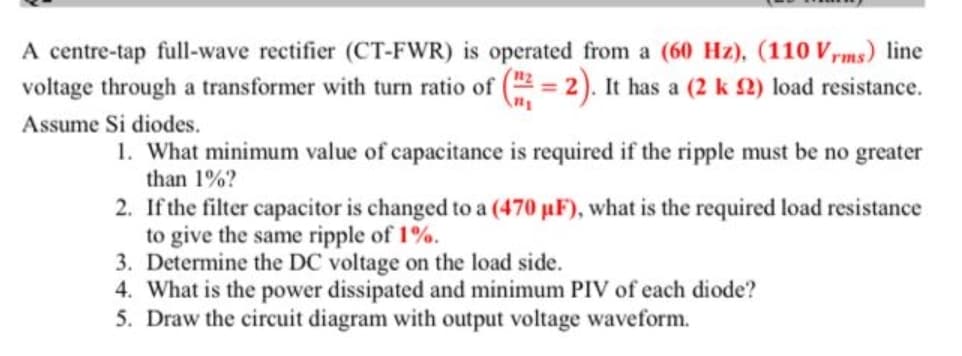
A centre-tap full-wave rectifier (CT-FWR) is operated from a (60 Hz), (110 Vrms) line voltage through a transformer with turn ratio of ( = 2). It has a (2 k 2) load resistance. Assume Si diodes. 1. What minimum value of capacitance is required if the ripple must be no greater than 1%? 2. If the filter capacitor is changed to a (470 µF), what is the required load resistance to give the same ripple of 1%. 3. Determine the DC voltage on the load side. 4. What is the power dissipated and minimum PIV of each diode? 5. Draw the circuit diagram with output voltage waveform.
A centre-tap full-wave rectifier (CT-FWR) is operated from a (60 Hz), (110 Vrms) line voltage through a transformer with turn ratio of ( = 2). It has a (2 k 2) load resistance. Assume Si diodes. 1. What minimum value of capacitance is required if the ripple must be no greater than 1%? 2. If the filter capacitor is changed to a (470 µF), what is the required load resistance to give the same ripple of 1%. 3. Determine the DC voltage on the load side. 4. What is the power dissipated and minimum PIV of each diode? 5. Draw the circuit diagram with output voltage waveform.

Introductory Circuit Analysis (13th Edition)
13th Edition
ISBN:9780133923605
Author:Robert L. Boylestad
Publisher:Robert L. Boylestad
Chapter1: Introduction
Section: Chapter Questions
Problem 1P: Visit your local library (at school or home) and describe the extent to which it provides literature...

Related questions
Question
Transcribed Image Text:A centre-tap full-wave rectifier (CT-FWR) is operated from a (60 Hz), (110 V,ms) line
voltage through a transformer with turn ratio of ( = 2). It has a (2 k 2) load resistance.
Assume Si diodes.
1. What minimum value of capacitance is required if the ripple must be no greater
than 1%?
2. If the filter capacitor is changed to a (470 µF), what is the required load resistance
to give the same ripple of 1%.
3. Determine the DC voltage on the load side.
4. What is the power dissipated and minimum PIV of each diode?
5. Draw the circuit diagram with output voltage waveform.
Expert Solution
This question has been solved!
Explore an expertly crafted, step-by-step solution for a thorough understanding of key concepts.

Step by step
Solved in 4 steps with 1 images

Knowledge Booster


Learn more about
Need a deep-dive on the concept behind this application? Look no further. Learn more about this topic, electrical-engineering and related others by exploring similar questions and additional content below.Recommended textbooks for you
Introductory Circuit Analysis (13th Edition)
Electrical Engineering
ISBN:
9780133923605
Author:
Robert L. Boylestad
Publisher:
PEARSON

Delmar's Standard Textbook Of Electricity
Electrical Engineering
ISBN:
9781337900348
Author:
Stephen L. Herman
Publisher:
Cengage Learning

Programmable Logic Controllers
Electrical Engineering
ISBN:
9780073373843
Author:
Frank D. Petruzella
Publisher:
McGraw-Hill Education
Introductory Circuit Analysis (13th Edition)
Electrical Engineering
ISBN:
9780133923605
Author:
Robert L. Boylestad
Publisher:
PEARSON
Delmar's Standard Textbook Of Electricity
Electrical Engineering
ISBN:
9781337900348
Author:
Stephen L. Herman
Publisher:
Cengage Learning
Programmable Logic Controllers
Electrical Engineering
ISBN:
9780073373843
Author:
Frank D. Petruzella
Publisher:
McGraw-Hill Education

Fundamentals of Electric Circuits
Electrical Engineering
ISBN:
9780078028229
Author:
Charles K Alexander, Matthew Sadiku
Publisher:
McGraw-Hill Education

Electric Circuits. (11th Edition)
Electrical Engineering
ISBN:
9780134746968
Author:
James W. Nilsson, Susan Riedel
Publisher:
PEARSON

Engineering Electromagnetics
Electrical Engineering
ISBN:
9780078028151
Author:
Hayt, William H. (william Hart), Jr, BUCK, John A.
Publisher:
Mcgraw-hill Education,