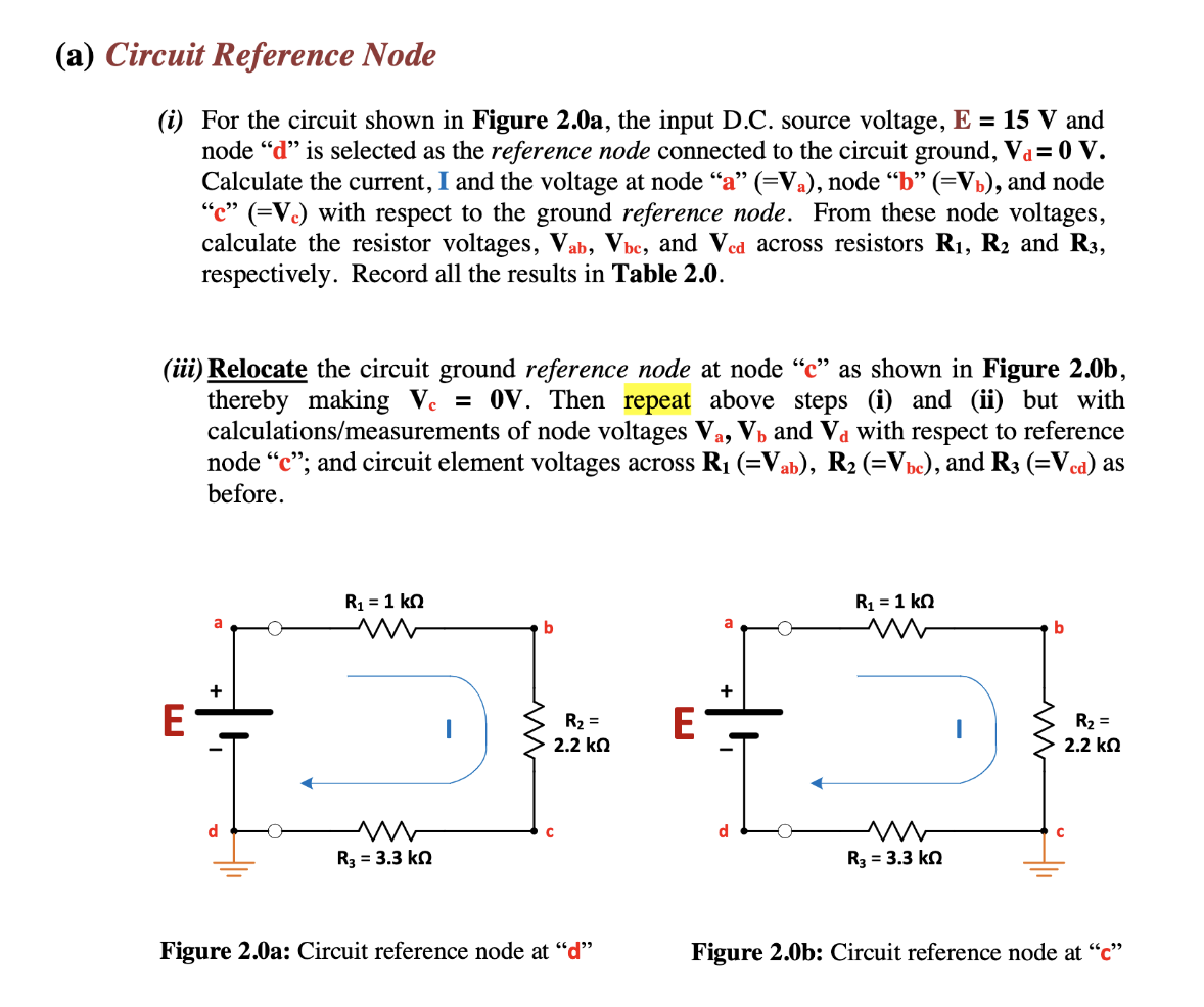
(a) Circuit Reference Node (i) For the circuit shown in Figure 2.0a, the input D.C. source voltage, E = 15 V and node "d" is selected as the reference node connected to the circuit ground, V₁ = 0 V. Calculate the current, I and the voltage at node "a" (=Va), node "b" (=V₁), and node "e" (=Vc) with respect to the ground reference node. From these node voltages, calculate the resistor voltages, Vab, Vbe, and Ved across resistors R₁, R₂ and R3, respectively. Record all the results in Table 2.0. (iii) Relocate the circuit ground reference node at node "c" as shown in Figure 2.0b, thereby making Vc = 0V. Then repeat above steps (i) and (ii) but with calculations/measurements of node voltages Va, V₁ and Va with respect to reference node "c"; and circuit element voltages across R₁ (=Vab), R₂ (=Vbc), and R3 (=Vca) as before. E d R₁ = 1 kn R₂ = 3.3 kn b с R₂ = 2.2 ΚΩ Figure 2.0a: Circuit reference node at "d" E d R₁ = 1 kn www R₂ = 3.3 k b R₂ = 2.2 ΚΩ C Figure 2.0b: Circuit reference node at "c"
(a) Circuit Reference Node (i) For the circuit shown in Figure 2.0a, the input D.C. source voltage, E = 15 V and node "d" is selected as the reference node connected to the circuit ground, V₁ = 0 V. Calculate the current, I and the voltage at node "a" (=Va), node "b" (=V₁), and node "e" (=Vc) with respect to the ground reference node. From these node voltages, calculate the resistor voltages, Vab, Vbe, and Ved across resistors R₁, R₂ and R3, respectively. Record all the results in Table 2.0. (iii) Relocate the circuit ground reference node at node "c" as shown in Figure 2.0b, thereby making Vc = 0V. Then repeat above steps (i) and (ii) but with calculations/measurements of node voltages Va, V₁ and Va with respect to reference node "c"; and circuit element voltages across R₁ (=Vab), R₂ (=Vbc), and R3 (=Vca) as before. E d R₁ = 1 kn R₂ = 3.3 kn b с R₂ = 2.2 ΚΩ Figure 2.0a: Circuit reference node at "d" E d R₁ = 1 kn www R₂ = 3.3 k b R₂ = 2.2 ΚΩ C Figure 2.0b: Circuit reference node at "c"

Introductory Circuit Analysis (13th Edition)
13th Edition
ISBN:9780133923605
Author:Robert L. Boylestad
Publisher:Robert L. Boylestad
Chapter1: Introduction
Section: Chapter Questions
Problem 1P: Visit your local library (at school or home) and describe the extent to which it provides literature...

Related questions
Question
100%
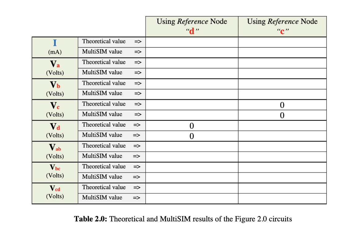
Please use parts (i) and (iii) to complete Table 2.0 for the circuit shown in Figure 2.0a and 2.0b, respectively. Please include all calculations done. Ignore the MultiSIM input sections when completing Table 2.0. Thank you very much!
Transcribed Image Text:(a) Circuit Reference Node
(i) For the circuit shown in Figure 2.0a, the input D.C. source voltage, E = 15 V and
node "d" is selected as the reference node connected to the circuit ground, Va= 0 V.
Calculate the current, I and the voltage at node "a" (=Va), node “b” (=V₁), and node
"c" (=Vc) with respect to the ground reference node. From these node voltages,
calculate the resistor voltages, Vab, Vbc, and Ved across resistors R₁, R2 and R3,
respectively. Record all the results in Table 2.0.
(iii) Relocate the circuit ground reference node at node "c" as shown in Figure 2.0b,
thereby making Vc = 0V. Then repeat above steps and (ii) but with
calculations/measurements of node voltages Va, V₁ and Và with respect to reference
node "c"; and circuit element voltages across R₁ (=Vab), R₂ (=Vbc), and R3 (=Vcd) as
before.
d
E
a
R₁ = 1 KQ
M
M
R3 = 3.3 kn
b
C
R₂ =
2.2 ΚΩ
Figure 2.0a: Circuit reference node at "d"
a
+
R₁ = 1 kn
m
www
R3 = 3.3 kQ
b
R₂ =
2.2 ΚΩ
Figure 2.0b: Circuit reference node at "c"
Transcribed Image Text:(mA)
Va
(Volts)
Vb
(Volts)
Vc
(Volts)
Vd
(Volts)
Vab
(Volts)
V bc
(Volts)
Vcd
(Volts)
Theoretical value
MultiSIM value
=>
Theoretical value =>
MultiSIM value
=>
Theoretical value =>
MultiSIM value
=>
Theoretical value =>
MultiSIM value
=>
Theoretical value =>
MultiSIM value =>
Theoretical value
MultiSIM value
Theoretical value
MultiSIM value
Theoretical value =>
MultiSIM value =>
=>
=>
=>
Using Reference Node
"d"
0
0
Using Reference Node
"C"
0
0
Table 2.0: Theoretical and MultiSIM results of the Figure 2.0 circuits
Expert Solution
This question has been solved!
Explore an expertly crafted, step-by-step solution for a thorough understanding of key concepts.

This is a popular solution!

Trending now
This is a popular solution!

Step by step
Solved in 6 steps with 6 images

Knowledge Booster


Learn more about
Need a deep-dive on the concept behind this application? Look no further. Learn more about this topic, electrical-engineering and related others by exploring similar questions and additional content below.Recommended textbooks for you
Introductory Circuit Analysis (13th Edition)
Electrical Engineering
ISBN:
9780133923605
Author:
Robert L. Boylestad
Publisher:
PEARSON

Delmar's Standard Textbook Of Electricity
Electrical Engineering
ISBN:
9781337900348
Author:
Stephen L. Herman
Publisher:
Cengage Learning

Programmable Logic Controllers
Electrical Engineering
ISBN:
9780073373843
Author:
Frank D. Petruzella
Publisher:
McGraw-Hill Education
Introductory Circuit Analysis (13th Edition)
Electrical Engineering
ISBN:
9780133923605
Author:
Robert L. Boylestad
Publisher:
PEARSON
Delmar's Standard Textbook Of Electricity
Electrical Engineering
ISBN:
9781337900348
Author:
Stephen L. Herman
Publisher:
Cengage Learning
Programmable Logic Controllers
Electrical Engineering
ISBN:
9780073373843
Author:
Frank D. Petruzella
Publisher:
McGraw-Hill Education

Fundamentals of Electric Circuits
Electrical Engineering
ISBN:
9780078028229
Author:
Charles K Alexander, Matthew Sadiku
Publisher:
McGraw-Hill Education

Electric Circuits. (11th Edition)
Electrical Engineering
ISBN:
9780134746968
Author:
James W. Nilsson, Susan Riedel
Publisher:
PEARSON

Engineering Electromagnetics
Electrical Engineering
ISBN:
9780078028151
Author:
Hayt, William H. (william Hart), Jr, BUCK, John A.
Publisher:
Mcgraw-hill Education,