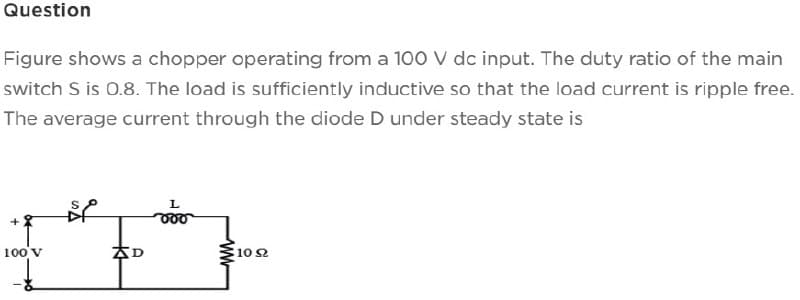
Question Figure shows a chopper operating from a 100 V dc input. The duty ratio of the main switch S is 0.8. The load is sufficiently inductive so that the load current is ripple free. The average current through the diode D under steady state is 100 V SP D L 10 92
Q: The electric field amplitude of a uniform plane wave propagating in z direction is 250 V/m. If E =…
A:
Q: 20 cos(10t + 1009) (+1 0.5 Η m www 10 Ω 0 F νο |
A:
Q: Q5/ A 3-phase, 415V, 4-pole, 50Hz star connected S.M has a synchronous impedance of 0.72+j6/phase.…
A: For a 3-phase star connected synchronous motor,Voltage, V=415 V.Pole, P=4.Frequency, f=50…
Q: The full bridge resonant inverter with bidirectional switches shown below is operating at a…
A: Given that ; Io = 88.2 A, R = 2 ohms, fo = 3.5 kHz, Vs = 220 V, C = 6 uF, And L = 50 uH .
Q: 1- Given the following two-degrees of freedom translational mechanical system, use the "by…
A: For the given mechanical translational system, the transfer function G(s) = X1(s)F(s) needs to be…
Q: Problem 4 Assume that a single-phase, two-winding transformer has a core loss of 1500 W. The…
A: As per the guidelines of Bartleby we suppose to answer first three subpart only for solution of…
Q: Examples and resolution of electrical protection coordination problems
A: We have to give examples and resolution of electrical protection coordination problems.
Q: A delta connected, balanced three phase load consisting of three impedances of 20 ohms 30 degrees is…
A:
Q: An uncharged capacitor and bulb are connected in series with a battery. Describe and explain what…
A: An uncharged capacitor and bulb are connected in series with a battery as shown below,
Q: e Q1: let the sequence x(n)= n³ 1≤n≤2 -2≤n<0 other wise 1-y₁(n)= 3x(3n+1) 2-y₂(n)=2u(-n-2)-x(n) 4-…
A: Given Data: A sequence of, xn=e-n2+11≤n≤2n3-2≤n<00Otherwise To Find: 1. Plot of y1n=3x3n+1 2.…
Q: A power plant has a maximum demand of 120 MW, load factor of 85% and the capacity factor of 60%,…
A: here we have to find the plant capacity and utilization factor.
Q: INSAT-2E was launched from 1. India 2. French Guiana 3. Peru 4. Mayotte
A: INSAT-2E was launched from?
Q: QUESTION 2 Assume Figure 2 is an ideal operating amplifier circuit. Show that the leftmost…
A: given condition is V1 = Vo - Vin to show the leftmost amplifier works…
Q: $ day 25 1.5 0.5 2.5 2 1.5 0.5 -0.5 0 1 2 3 1 (sec) x2(1) t(sec) 4 b) Use MALAB code to compute the…
A: Solution: given data: →y(t)=X1t*X2t Determine : here using Matlab code compute Convolution…
Q: OUTCOME(S) INSTRUCTIONS DELIVERABLES Discuss the environmental sustainability issues in…
A: Introduction:The rapid growth of the semiconductor industry, driven by the production of…
Q: Find the hybrid parameters for the two-port network shown in Fig. 7.37(a).
A: It is given that:
Q: Find the average value of signal shown below a)-0.66 +3 X(t) b) 0 π/2 7 37/2 2π c) 0.25 d) none
A:
Q: Problem 3: As they were small please answer all a) What type of amplifier configuration provides…
A:
Q: 2. A single phase, 60Hz, 200-km medium nominal- transmission line receives 700 MW at 0.95 lagging pf…
A: Given Data: A single phase, 200km, medium nominal-π transmission line with, Sending end power…
Q: Find the closed loop transfer function for the following block diagram by using block diagram…
A: it is asked to find the closed loop transfer function by block diagram reduction techniques
Q: 13. For the following circuit, F 3 ΚΩ www 1 km2 +10 mA the power absorbed by the 3k2 resistor is:…
A: The circuit is,
Q: Q1:let the sequence x(n)= 3n 0 -3<n≤0 other wise 1-y(n)=-3x(-n-2) 2-y₂(n)=p(n-2))+x(n) 3- can you…
A:
Q: A 400 MVA synchronous machine has H₁ = 4.6 MJ/MVA and a 1200 MVA machine has H₂=3.0 MJ/MVA. The two…
A: It is given that: H1=4.6 MJMVA ,S1=400 MVAH2=3.0 MJMVA ,S2=1200 MVASbase=100 MVA
Q: (5 Points) Find 11. Vs = 10 V VD1(ON) = VD2(ON) = 0.7 V Rs = 10 Ohm Vs O 0.07 A (+ 0.14 A O 1 A O2 A…
A:
Q: What will be the voltage of a battery if a charge of 4 × 10⁻⁴ coulomb resides on the positive…
A:
Q: 10. Determine the power density on an earth station from a 5-W satellite source. That is 22,000 mi…
A: here we have to find the power density.
Q: 5) Find the closed loop transfer function for the following block diagram by using block diagram…
A:
Q: Calculate the noise margins for a logic gate with the following logic levels: VIL = 1.0 V, VIH = 3.7…
A:
Q: Construct a 5-to-32-line decoder with enable by using 3-to-8 and 2-to-4-line decoders with enables
A: The 5 to 32 line decoder needs to be designed by using the 3 to 8 decoder for enabling and 2 to 4…
Q: 2. Find the cascaded voltage gain of the following amplifier chain. (V-30V) wolod citi!
A: For the given circuit the voltage gain of the cascaded system needs to be calculated. The first…
Q: The half-bridge resonant inverter with bidirectional switches is operated at a frequency of fo =3…
A: In this question we need to choose a correct option
Q: Question 2. A three-phase, delta-connected, 2-pole 1000 V, 50Hz asynchronous motor rotates at 2920…
A: The given circuit diagram is shown below, Here,Pole, P=2.Voltage, V=1000 V.Frequency, f=50 Hz.Speed…
Q: Assume Figure 2 is an ideal operating amplifier circuit. Show that the leftmost operational works as…
A: The leftmost circuit working needs to be analyzed and needs to prove it as a subtractor circuit.
Q: Discuss briefly the following Boolean Algebra terms and give at least five ( 5 ) examples each : a.…
A: Here asked to explain briefly about Boolean algebra and mention atleast 5 examples of a)SOP b)POS
Q: Determine the input impedance of the circuit in Fig. 9.24 at = 10 rad/s.
A: It is given that:
Q: + X R L For the RL circuit, find the mathematical model (input-output relationship) if the output is…
A: here we have to find the mathematical model of the circuit.
Q: For the circuit shown find the impedance phase angle Z (in degrees) i = 0.02 sin(157t +40)
A: Circuit diagram is given as,
Q: Find I1 and I2.
A: For the given magnetically coupled circuit the value of unknown current I1 and I2 needs to be…
Q: Find the summation: E-o 8(n + 5)³√/cos(3n)
A: The above question is based on the properties of discrete impulse signal. Note that angle has been…
Q: Given this question for PMDC motor For Full-load and Half-load states, write the motor Torque -…
A: To obtain the motor Torque-Speed transfer function for both the full-load and half-load states, we…
Q: Question 3. A three-phase impedance load balanced A a connected load in parallel with a balanced y…
A: Given,Impedances,Z∆=6+6j Ω.ZY=2+2j Ω.Zn=1j Ω.Voltages,V0=10∠60° V.V1=100∠0° V.V2=15∠200° V.
Q: c) If in figure 3.1 a npn BJT transistor with a current gain ß = 75 is used and RB1 = 100 kohm, RB2…
A: For the given BJT CE amplifier circuit the value of the DC parameters needs to be calculated.
Q: Consider the following step response of a system. We want to find a model that represents this…
A: In this question we need to find the following the following Transfer function of the given system…
Q: Design a diople Anntenna at a frequency of 2.5ghz. (calculate length etc) Need Asap just 5 Mints…
A: Length (L) = (Speed of light) / (2 x Frequency) Given; Frequency = 2.5 GHz Speed of light = 3 x…
Q: The trigonometric Fourier series of an even function does not have the (A) dc term (B) cosine terms…
A: We know that, trigonometry Fourier series is period signal. It is represents a periodic function as…
Q: Define input impedance and its importance in electronic circuits and systems.
A: Input impedance is a fundamental concept in electronic circuits and systems. It refers to the…
Q: 13. For the given circuit below, find Vs 0.2 Ω 0.04 Ω 0.3 Ω j0.15Ω wwwm V₂ 10 W 0.9 pf lagging 15 W…
A:
Q: At a certain location of an electrical system, the available short circuit MVA is 10 at 110 kV while…
A: Old short circuit base MVA, Sbold=10 MVA, Old base voltage, Vold=110 kV. New base MVA, Sbnew=20 MVA,…
Q: Question Two uniform line charges of density p=4 nC/m lie in x=0 plane y=+4m. Find E at (4,0,10) m.
A: Step-1->
Q: Implement the following Boolean function using a (1) multiplexer, (2) then using a decoder and…
A: Need to implement the given boolean function using the multiplexer and decoder along with OR gate.
Step by step
Solved in 3 steps with 1 images
- The temperature dependence of resistance is also quantified by the relation R2=R1[ 1+(T2T1) ] where R1 and R2 are the resistances at temperatures T1 and T2, respectively, and is known as the temperature coefficient of resistance. If a copper wire has a resistance of 55 at 20C, find the maximum permissible operating temperature of the wire if its resistance is to increase by at most 20. Take the temperature coefficient at 20C to be =0.00382.Draw the circuit diagram of a single phase full-wave uncontrolledrectifier with R-load. Describe its principle of operation. Draw thewaveforms of: input voltage, voltage across the load, current throughthe diodes and their voltage. Write the expressions for: the averageoutput voltage Vd, the maximum reverse voltage across the diode and thestandard transformer power. Describe what the difference will be if acapacitor is added in parallel with the load at the output.A diode whose internal resistance is 20 ohms is to supply power to a 1000-ohm load from a 110V(rms) source of supply. Calculate the peak load current, dc load current. and determine the percent regulation from no load to the given load. a.) Peak Load Current= 120.8mA; DC load current=25.5mA b.) Peak Load Current= 133.3mA; DC load current=29.4mA c.) Peak Load Current= 144.3mA; DC load current=34.7mA d.) Peak Load Current= 152.5mA; DC load current= 48.5mA
- In a 1-phase full wave bridge rectifier with Vs = Vm sin ωt, with R load & ideal diodes. The expression for the average value of the output voltage is 2Vm/π Select one: True Falsea) Use the diode’s characteristic equation,ID=Is exp(VD/VT), to determine the currentsourceIso that the output voltage is 1.5 V. b) If a load is attached to the output that draws 1 mA, what is the output voltage? c) If the circuit heats up to 40◦C, what is the output voltage without a load?please solve parts d and e Q.1 A single-phase diode bridge rectifier is connected to a grid with rms voltage V, 230V at 50 Hz. Assume that the load is highly inductive, so it could be represented by a constant dc current, Id = 10A. a) Sketch the load voltage and find the average voltage of the load? b) Sketch the source current (grid. AC side) and find the rms value of the source current? c) Determine the fundamental source current and the first three harmonics? Assume Ish_rms ³ 0.91a/h for odd hand 0 otherwise? d) Determine the input power (active)? e) Determine the power factor?
- An FWR using a centre-tapped Transformer Supplies an average voltage of 120V to a 250 kΩ load Calculate (a) the peak value of output voltage (b) The required Transformer secondary voltage (rms value) (c) Average Current delivered to load (d) Average current through each of the diodes. (e) Peak Current through each of the diodes (f) PIV requirements for each of the diodes. AC supply voltage is 230V and assume ideal diodes.Derive the current equations for the circuit shown below, using the labels as shown.Note that rz here is a model of the parasitic imperfection of the Zener diode.a) IL = ?b) II = ?c) IZ = ?d) What impact does rz have on VL?Q.1 A single-phase diode bridge rectifier is connected to a grid with rms voltage V, 230V at 50 Hz. Assume that the load is highly inductive, so it could be represented by a constant dc current, Id = 10A. a) Sketch the load voltage and find the average voltage of the load? b) Sketch the source current (grid. AC side) and find the rms value of the source current? c) Determine the fundamental source current and the first three harmonics? Assume Ish_rms ³ 0.91a/h for odd hand 0 otherwise?
- The circuit in Figure is a complementary output rectifier. If vs = 26√2sin[120πt]V,assumingV? =0.6V for each diode. Determine the average and rms of complimentary outputs VO+ and VO-. . Also derive formfactor and ripple factor each output.In the figure, SCR semiconductor switched rectifier to a 220 Vrms ac source at 50 Hz, at load Vdc = 100 V, R = 8 Ω and has an inductor large enough to supply continuous current. (a) Trigger angle α = 25o determine the total power absorbed by the load. (b) If the inductance value is 30 mH, the change value from the top Determine.Consider a peak rectifier ted by a 50 Hz sinusoid having a peak value Vp-100 V. Let the load resistance R 10 kohm. The value of the capacitance C that will result in a peak to peak ripple of 3 V is: