a) Design the circuit of Figure Q2 for a voltage gain of 20 and a power budget of 1mW with VDD = 1.8 V. Assume M₁ operates at the edge of saturation if the input common-mode level is 1 V. Also, assume unCox = 100 μA/V², µpCox = 50 μA/V², VTH,n = 0.5 V, VTH,p= -0.4 V, In = 0.1 V-¹ and Ip = 0.2 V-¹. VDD M3 A - Vout Vin10- Vin2 P Figure Q2 b) Determine the output impedance formula (no values needed) of the circuit in Figure Q2. Assume gmro >> 1. M₁1₁ M2 MA Iss
a) Design the circuit of Figure Q2 for a voltage gain of 20 and a power budget of 1mW with VDD = 1.8 V. Assume M₁ operates at the edge of saturation if the input common-mode level is 1 V. Also, assume unCox = 100 μA/V², µpCox = 50 μA/V², VTH,n = 0.5 V, VTH,p= -0.4 V, In = 0.1 V-¹ and Ip = 0.2 V-¹. VDD M3 A - Vout Vin10- Vin2 P Figure Q2 b) Determine the output impedance formula (no values needed) of the circuit in Figure Q2. Assume gmro >> 1. M₁1₁ M2 MA Iss

Introductory Circuit Analysis (13th Edition)
13th Edition
ISBN:9780133923605
Author:Robert L. Boylestad
Publisher:Robert L. Boylestad
Chapter1: Introduction
Section: Chapter Questions
Problem 1P: Visit your local library (at school or home) and describe the extent to which it provides literature...

Related questions
Question
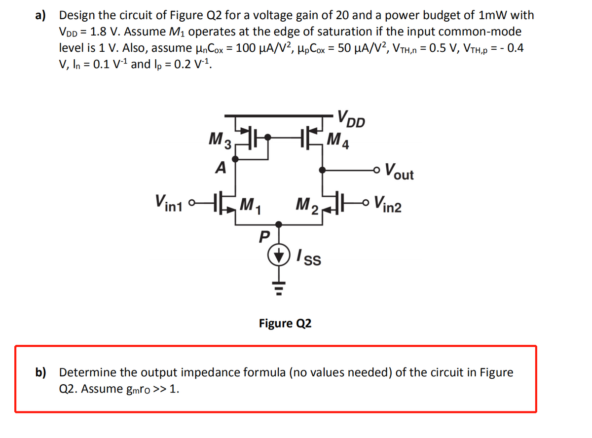
Transcribed Image Text:a) Design the circuit of Figure Q2 for a voltage gain of 20 and a power budget of 1mW with
VDD = 1.8 V. Assume M₁ operates at the edge of saturation if the input common-mode
level is 1 V. Also, assume µnCox = 100 µA/V², µµCox = 50 µA/V², VTH,n = 0.5 V, VTH,p = -0.4
V, In = 0.1 V-¹ and lp = 0.2 V-¹.
VDD
M3
HEMA
A
Vin10
M₂ Vin2
P
Iss
Figure Q2
b) Determine the output impedance formula (no values needed) of the circuit in Figure
Q2. Assume gmro >> 1.
M
Vout
Expert Solution
This question has been solved!
Explore an expertly crafted, step-by-step solution for a thorough understanding of key concepts.

Step by step
Solved in 3 steps with 3 images

Knowledge Booster


Learn more about
Need a deep-dive on the concept behind this application? Look no further. Learn more about this topic, electrical-engineering and related others by exploring similar questions and additional content below.Recommended textbooks for you
Introductory Circuit Analysis (13th Edition)
Electrical Engineering
ISBN:
9780133923605
Author:
Robert L. Boylestad
Publisher:
PEARSON

Delmar's Standard Textbook Of Electricity
Electrical Engineering
ISBN:
9781337900348
Author:
Stephen L. Herman
Publisher:
Cengage Learning

Programmable Logic Controllers
Electrical Engineering
ISBN:
9780073373843
Author:
Frank D. Petruzella
Publisher:
McGraw-Hill Education
Introductory Circuit Analysis (13th Edition)
Electrical Engineering
ISBN:
9780133923605
Author:
Robert L. Boylestad
Publisher:
PEARSON
Delmar's Standard Textbook Of Electricity
Electrical Engineering
ISBN:
9781337900348
Author:
Stephen L. Herman
Publisher:
Cengage Learning
Programmable Logic Controllers
Electrical Engineering
ISBN:
9780073373843
Author:
Frank D. Petruzella
Publisher:
McGraw-Hill Education

Fundamentals of Electric Circuits
Electrical Engineering
ISBN:
9780078028229
Author:
Charles K Alexander, Matthew Sadiku
Publisher:
McGraw-Hill Education

Electric Circuits. (11th Edition)
Electrical Engineering
ISBN:
9780134746968
Author:
James W. Nilsson, Susan Riedel
Publisher:
PEARSON

Engineering Electromagnetics
Electrical Engineering
ISBN:
9780078028151
Author:
Hayt, William H. (william Hart), Jr, BUCK, John A.
Publisher:
Mcgraw-hill Education,