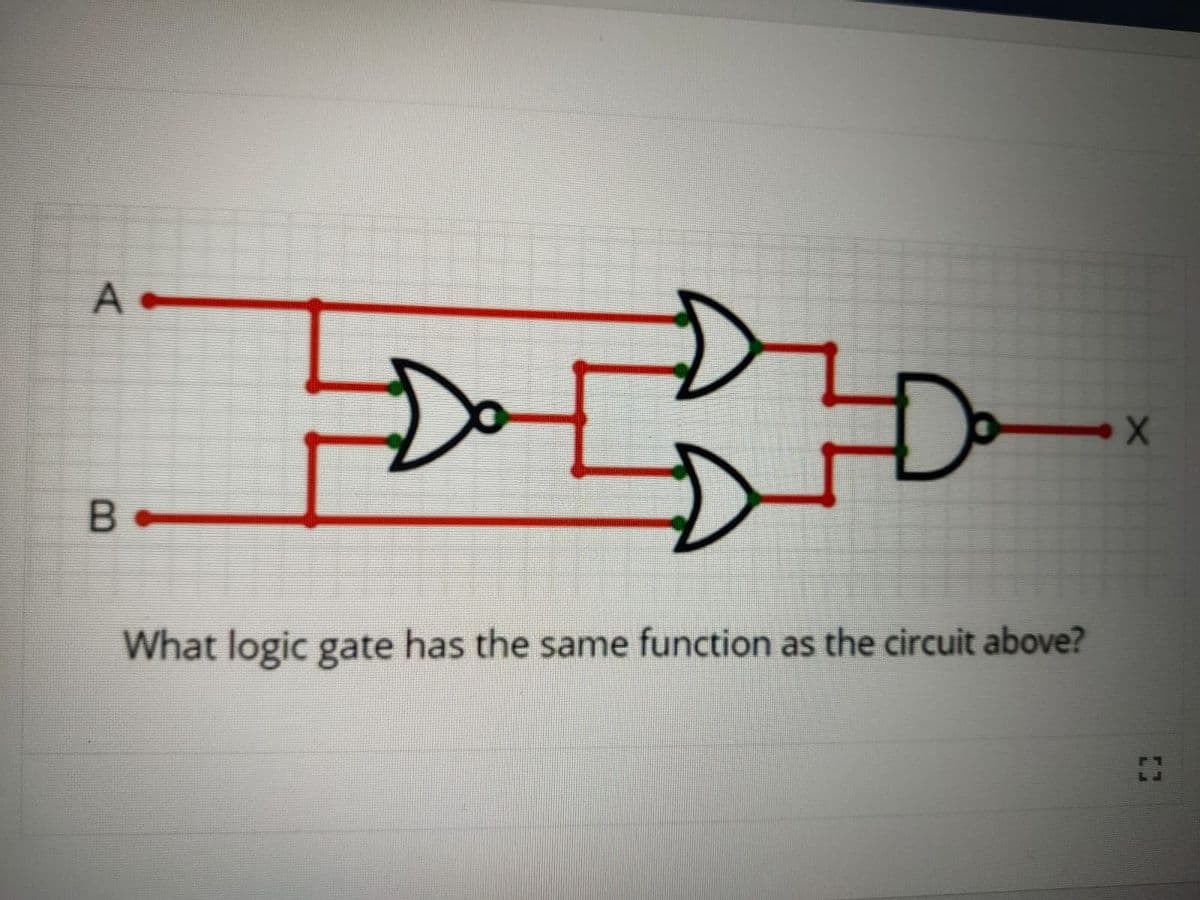
A- Do Ja B What logic gate has the same function as the circuit above? X


Q: Exercises. tzo (1) ota + 2 4V 6F Find and sketch D(H) and i(t). 3.1 MM R2F $32
A: Since you have asked multiple questions in a single request, we will be answering only the 1st…
Q: Q33-Q37 refer to the table below: The line currents in a balanced 60 Hz, 4-wire system has the…
A: Note :- As per guidelines we are supposed to answer only 3 sub-parts. So please post separately rest…
Q: How many wattmeters would be needed to measure the total three-phase power in a balanced three-phase…
A: In this questions, we need to tell about the how many wattmeter is required to measur the power in…
Q: A 460VAC rated, 60 Hz, 125-Hp Three-phase induction type motor is to be connected for…
A:
Q: A three-phase motor is connected to a balanced three-phase supply. Meters placed in the circuit…
A: In this question, We need to determine the total apparent power of the load? We know apparent…
Q: Determine the charging current (Ic) at 50 Hz of a single-conductor EHV transmission line having…
A:
Q: 1. Three circuit elements in parallel have admittance of 6.32-40 mS at a frequency of 2 kHz. If one…
A:
Q: Two single-phase transformers, one of 100 kVA and the other of 50 KVA are connected in parallel to…
A: Given data, Rating of transformer S1=100 KVA, S2=50 KVA Resistances are given 2% and 5% Reactance's…
Q: The open circuit test in a 100 kVA, 2000/200 V, 50 Hz, single phase transformer gives 200 V, 90 A, 5…
A:
Q: Q.1: Establish Zbus matrix for the system shown in figure below using Direct Method and add the…
A: given system with impedances. To find Zbus a step by step procedure is followed based on the…
Q: Solve for the power of each individual resistors. 12 V 5 A 20 V + 20 V Io + 8 V 3 A 3 A
A:
Q: Q38-Q40 refer to the table below: The voltage in a 60 Hz, 1-phase system has the following harmonic…
A: Given three harmonics with their RMS voltage values of a single phase 60 Hz system. Let Vn be the…
Q: V₂ (s) For the network shown Figure 1, determine the voltage transfer ratio V₁(s) gain, poles and…
A: Applying KCL at V, we get V1s+V-V2(s)1+V-V1(s)1=0 V[s+1+1]=V2(s)+V1(s) V=V1(s)+V2(s)s+2------1 Again…
Q: Find hybrid parameters for the network in figure 3 ΤΩ ΖΩ METW ΖΩ Μ Figure 3 ΤΩ 41₁ Ω
A:
Q: 1. For the circuit shown in Figure 7.1, determine apparent power S, real power P, reactive power Q…
A:
Q: PROBLEM: Given the system represented in state space by Eqs. (4.108), 2 X = --0- x+ -3 y (1 3x x(0)…
A:
Q: Note: Answer Four Questions only Q1: A three-phase balanced source voltages, operating with a 380 -V…
A:
Q: Q2// Find the current at 10 22 by using thevenin's theorem? 292 122 10v= 592 VIL 1092 +1+ 20v
A:
Q: H.W. (1) Find the total admittance and impedance of the parallel network of Fig. 23 10 kn Z₁ XL R6k0…
A:
Q: he ratings of a single-phase three-winding transformer are as follows: *primary winding: 300 MVA,…
A: Base MVA=300 MVARated primary side voltage=14 kV→terminal 1Rated secondary winding voltage= 200…
Q: Q3: Find hybrid parameters for the network in fic 192 292 Figure 2 292 Figure 3 192 41₁1 1₂ 292 +
A: In this question, We need to determine the h parameters of the given system?
Q: ltage as shown in Fig. 1. Calculate: O the phase voltage and power factor the currents 11, 12, 13,…
A:
Q: C is 7.5 mH 12 Q2 ?For the circuit shown above, what is the maximum average power that can be…
A: In this question we need to find a maximum average power transfer to load.
Q: How a magnitude Bode plot is constructed knowing the transfer function of the system. H(s) s4…
A: The given transfer function is shown below.…
Q: Problem 19. A single-phase power line comprises two conductors each with a radius 8.0 mm and spaced…
A: Given a single phase power line comprises two conductors with, Radius, r = 8.0 mm = 8×10⁻³ m Spaced…
Q: Determine the inverse z-transform of X(z)= 1 1-1.52-1+0.5z-2
A:
Q: A sample of Si at 300 K doped with 10¹6 cm³ Boron, with recombination lifetime 3 us. It is exposed…
A: Brief description: For the given boron doping, generation rate with recombination lifetime we need…
Q: The physical address of the following memory location specified in the instruction MOV [BX+0200H],…
A: Procedure to find physical address MOV = DS*100 MOV BX = DS*10 +BX MOV BX+0200H = DS *10 +BX…
Q: Question: 15 Analog computer works on the supply of (A) Physical strength (B) Natural strength…
A:
Q: 13.8 kV Source Load m 1.5KG
A: Given data, Circuit diagram is given as,
Q: 1. Calculate the coil inductance L2, If L1= 50 mH, L3 = 25 mH, L4= 20 mH, L5= 30 mH and LAB = 18.75…
A: Leq is calculated as then from Leq calculate the value of L2
Q: 2. Determine the nominal resistance values of these resistors, given their band colors, and also…
A: Carbon resitance or color code resistancs is calculated as given below by using table
Q: Capacitive Comparison Bridge and inductive Comparison Bridge
A: Capacitance Comparison Bridge Ratio arms R1, R2 are resistive. C3 is in series with R3 Cx is the…
Q: 369-Vrms, 60-Hz supply serves a load that is 9 kW (resistive), 9 KVAR (capacitive), and 13 kVAR…
A: Given, Vs = 369 Vrms, F = 60 Hz, Power = 9 Kw, Capacitive reactive power = 9 KVAR, Inductive power =…
Q: 1+ 8 Ω + V + 13 τῆς 30 V 3 Ω Determine the following: 1. The current i1, 12, 13 2. The power…
A:
Q: P is P 0.8 pf lagging V 0.9 pf lagging ?For the circuit shown above, what is the magnitude of the…
A: A closed path, where electric current can flow defined as an electric circuit. It is various…
Q: 12 V R₁ ww C Data: C = ²F; R₁ = R₂= 6 N R₂ The switch is open for a long time before t = 0. At t= 0,…
A:
Q: :An industrial heater has a nameplate that reads Vrms 219 Hz 50 kVA 106 lagging 0.82 ?What is the…
A: Brief description: For the above given question we need to calculate the value of reactive power.…
Q: Find the laplace transform ol (22) of е-е
A:
Q: The switch in the given figure has been in position A for a long time. Assume the switch moves…
A: Brief description: For the above given question we need to calculate the value of initial voltage on…
Q: Question No.95 What is the number of right half plane poles in closed-loop transfer function: C(s)…
A: Given the closed-loop transfer function, CsRs=505s5+35s4+30s3+210s2+40s+280
Q: The input voltage of a Boost converter is 10V, the duty cycle of the boost converter is 0.25. What…
A: Brief description: For the above given question we need to calculate the value of output voltage of…
Q: For the flat solar collector shown in the figure. Determine the angle of azimuth-sun pareol (x) and…
A:
Q: pole, 50Hz, 11KV, turbo generator is rated 100 MW and 0.85 power factor lagging. The machine rotor…
A: Given, P =4f =50 HzV = 11 KVP= 75 MWcosϕ = 0.85J= 9000 Kg-m2 ω =4πfP =4π×504 = 50π rad/secK = 12Jω2…
Q: or the transfer function: 1 G(s) = s² + s +1 nd the (a) impulse response (b) step response to this…
A:
Q: Question 4: Determine the average power delivered and Power factor to network having the following…
A:
Q: c) In a CE amplifier: is it important to pay attenti when choosing the value of the bypass capacitor…
A: In this question we will write importance of bypass capacitor in common emitter amplifier....
Q: Problem 6. Find the conductance of a conductor of resistance (a) 10 S2, (b) 5 ks and (c) 100 m2.
A: Given, Conductors of resistance, aR=10 Ωb R=5 kΩc R=100 mΩ
Q: 2. Find out the inductance B in micro Henry, If L12 = 7.5 mH, A= 10 mH, C=25 mH, D=12 H and E=30 mH.…
A: given here a inductor circuit and asked to fine the inductance B in micro henry let us take 3…
Q: Consider the following three Phase balanced Circuit 210 20⁰ Vrms jasn 210/120⁰ Vrms 24-321 jost mm…
A: The three-phase delta connected load is shown below: The per-phase equivalent load impedance will…

Step by step
Solved in 2 steps with 2 images


- Answer the following questions: i. If a 3-input XOR gate has eight input possibilities, how many of those possibilities will result in a HIGH output? ii. What type of logic circuit is represented by the figure 4 shown below?PLSS ANSWER IN 10MINS Draw the complete logic diagram from the given logic equation, maximum of 2 inputs per gates used. Label the inputs and output properly.F = X'YZ+XY"Z(+)(XZ')'Q.4 Draw the logic diagram to implement the following expression with minimum number ofNAND gates. (A+B'+C')whole bar
- Realize the following function ; " on the image " using a(a) 4-to-1 multiplexer, and draw the logic diagram.(b) 8-to-1 multiplexer, and draw the logic diagram.You may use external gates if needed.Draw logic diagrams (network of gates) of the circuits that implement the original and simplifiedexpressions of the following:a’bc + abc’ + abc + a’bc’Build the logic circuit for the function F1 = XYZ + YŽ + YZ using PAL
- Q.) List external resources to be used for building a digital logic gate. (just a list of external resources used for building it not an explanation of it)F(A,B,C,D) = (B'+D')(A+C'D)+BCD' 1. Find Minterms and Maxter, in short notation 2. Draw logic diagram(a) Draw the logic diagram of a 3 × 8 decoder using two 2 × 4 decoders.