(a) Find the Q-point (VGs, Vos, ID) for the transistor for R₁ = 1000 k, R₂ = 2200 kg, R3 = 240 KS2, R4 = 120 k2, and VDD = 10V. Assume that KN'=100μA/V², VTN=0.75V and W/L=6/1. (b) Repeat for W/L=12/1 M FR₂ W R₁ W 10 W R4 FR3 VDD
(a) Find the Q-point (VGs, Vos, ID) for the transistor for R₁ = 1000 k, R₂ = 2200 kg, R3 = 240 KS2, R4 = 120 k2, and VDD = 10V. Assume that KN'=100μA/V², VTN=0.75V and W/L=6/1. (b) Repeat for W/L=12/1 M FR₂ W R₁ W 10 W R4 FR3 VDD

Delmar's Standard Textbook Of Electricity
7th Edition
ISBN:9781337900348
Author:Stephen L. Herman
Publisher:Stephen L. Herman
Chapter29: Dc Generators
Section: Chapter Questions
Problem 16RQ: Explain the difference between cumulative- and differential-compounded connections.

Related questions
Question
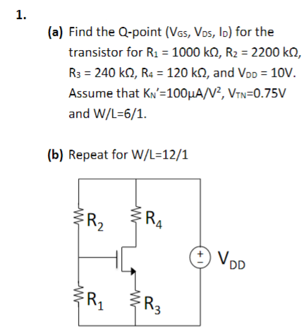
Transcribed Image Text:1.
(a) Find the Q-point (VGS, VDS, ID) for the
transistor for R₁ = 1000 kQ2, R₂ = 2200 kQ2,
R3 = 240 KS2, R4 = 120 k, and VDD = 10V.
Assume that KN'=100μA/V², VTN=0.75V
and W/L=6/1.
(b) Repeat for W/L=12/1
w
W
R₂
R₁
W
w
RA
FR3
+1
VDD
Expert Solution
This question has been solved!
Explore an expertly crafted, step-by-step solution for a thorough understanding of key concepts.

Step by step
Solved in 3 steps with 3 images

Knowledge Booster


Learn more about
Need a deep-dive on the concept behind this application? Look no further. Learn more about this topic, electrical-engineering and related others by exploring similar questions and additional content below.Recommended textbooks for you
Delmar's Standard Textbook Of Electricity
Electrical Engineering
ISBN:
9781337900348
Author:
Stephen L. Herman
Publisher:
Cengage Learning
Delmar's Standard Textbook Of Electricity
Electrical Engineering
ISBN:
9781337900348
Author:
Stephen L. Herman
Publisher:
Cengage Learning