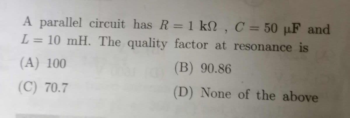
A parallel circuit has R = 1 kN , C = 50 µF and L = 10 mH. The quality factor at resonance is %3D %3D (A) 100 (B) 90.86 (C) 70.7 (D) None of the above


Q: 7. Given the following particulars: R_ = 40 N, Rc= 20 N, L = 0.254 H, C = 40 µF. Calculate: %3D a.…
A:
Q: 2) Construct the Bode magnitude & phase plots for: H(s) = 6(s+2)/[(s+1)(s+5)]
A: For the given transfer function, we have to construct the bode magnitude and phase plot.…
Q: For the series RLC circuit shown, the frequency of the voltage source v, = 20cos(@ot) V is adjusted…
A: In the circuit, Resistance, inductance and capacitance are connected in series. At resonance XL =…
Q: A series resonant circuit
A: Resonance in circuit- When inductive reactance of a circuit becomes equals to to capacitive…
Q: 4. A circuit consisting of a coil of resistance 122 and inductance 0.15 H in series with a capacitor…
A: Given, A series LC circuit with Resistance of coil, R=12 Ω Inductance, L=0.15 H Capacitance, C=12 μF…
Q: Bode plots for 4 different dynamic systems are reflected on the same graph. Please try to find out…
A: The transfer function from the bode plot can be derived by calculating the cut-off frequency of the…
Q: Draw the asymptotes of the Bode plots for the systems having a transfer function K G(s) = (T,s +…
A: Bode plot of given tranfer function Transfer function G(s) = K/(1+T1s) (1+T2s) Where T1= 2, T2=0.2…
Q: 20. In a series RLC circuit, which quality factor has the steepest magnitude response curve near…
A:
Q: -Sketch the magnitude and phase Bode plots for the transfer function 100(s + 1) H(s) = s(s + 10)
A:
Q: Sketch the ASYMPTOTIC Bode Plots both magnitude and phase for the following transfer function:…
A:
Q: Q3/ Plot the Bode diagram of the below system 0. 1s(s+ 5) (s + 6)(s + 2) G(s)
A: Control systems are represented by transfer function. This can be written in both time domain and…
Q: 5.8 For a parallel RLC resonant circuit, the damped frequency is V8 r/s and bandwidth is 2 r/s. What…
A: According to the question we have to find the value of the resonance frequency.
Q: (a) Find the H(s) with the following hand-sketched Bode Magnitude plot.
A: (a) We have to find the H(s) for the following Bode magnitude plot: Figure-(1) (b) We have to find…
Q: Draw the bode plot for this system K G(s) = s3 + 10s2 + 49s + 150
A: In the question Open loop transfer function is given. Draw a bode plot i.e magnitude plot and phase…
Q: 8 A voltage v(t) = 100 sinot is applied to a series RLC circuit. At the resonant frequency of the…
A: In this question, we need to determine the resonance frequency, upper and lower cut off frequency,…
Q: If the resonant frequency in a series RLC circuit is 50kHz along with a bandwidth of 1kHz, find the…
A: Given: Series RLC circuit having Resonant frequency, fr=50 kHz Bandwidth, BW=1 kHz
Q: QI: Plot the Bode for the following system using the Analytical method on semi-log paper. (s + 1)(s…
A:
Q: Plot the Bode for the following system using the Analytical method on semi-log paper. (s + 1)(s +…
A:
Q: A parallel RLC circuit has R = 5000 ohms, L = 8 mH and C = 60 microF. Determine a. The resonant…
A:
Q: Question 4 For RLC circuit that has Q-factor of 4.5 and inductor reactance of 22.5 Ohm, the value of…
A: Given for a RLC circuit, Q- factor, Q=4.5 Inductor reactance, XL=ωL=22.5 Ω
Q: 108000*(s+1)(s+15)/((s+0.1)(s+2.5)(s+120)(s+240)) draw bode plot by hand
A: We need to draw bode plot of the given transfer function by hand. The Transfer function is:…
Q: Sketch the asymptotes for the Bode plots of systems with the transfer functions (a) 100, (b) 1000/(s…
A: Control systems are represented by transfer function. This can be written in both time domain and…
Q: An electronic system requires a series RLC circuit to perform signal filtering. If the RLC circuit…
A:
Q: determine the transfer function of the given system vo(s)/vi(s)for the given system.output is…
A: Transfer function :- ratio of Laplace of output to Laplace of input is called transfer function…
Q: Q1) Sketch Bode plots for 10000 s (a) L(s) = (s+100)2
A: Dear student as per our guidelines we are supposed to solve only one question.kindly repost other…
Q: A series RLC circuit consists of a resistance of 430 ohm, inductance of 42 mH and a capacitance of…
A: We have an RLC circuit as, Resistance (R) = 430 Ω Inductance (L) = 42 mH = 42 * 10-3 H Capacitance…
Q: Q3/ Plot the Bode diagram of the below system 0. 1s(s + 5) G(s) (s + 6)(s + 2)
A: Control systems are represented by transfer function. This can be written in both time domain and…
Q: A series circuit consists of a 120V, 50HZ source, a 300 resistor, a 20mH inductance, and a…
A: In this question , we will find capacitance value for series resonance...
Q: .For the series RLC circuit shown below, find the resonant frequency wo = 2nfo. Also obtain the…
A:
Q: A series RLC circuit consists of R = 1000 ohms, L = 100 mH and C = 10 picoFarads. The applied…
A: RLC circuit in series A resistor, inductor, and capacitor are connected in series across a voltage…
Q: A series RLC resonant circuit has an inductance equal to 5 mH, and capacitance equal to 4.7 micoF.…
A:
Q: has capacitance of 0.3µF, inductor with inductance 24mH and resistance 372. Calculate the value of…
A: Resonant frequency given by fr = 1/2π√LC Quality factor Q= 2πfrL/R
Q: 2. Given that the second order overdamped circuit + Vin (0 has the following response to a…
A: The time for completer transient response decay is calculated as shown below
Q: for the system G(s) = S(S+1)(0.02S+1) 1. Draw bode plots. 2. Is the system stable or not. 3. Find…
A: GAIN MARGIN: The additional gain, which can be introduced into a system without affecting its…
Q: Q1) Sketch Bode plots for 10000 s (a) L(s) = %3D (s+100)² s+8 (b) L(s) = s2+6s+8 1 (c) L(s) =…
A: (a) Write the given transfer function in terms of angular frequency.
Q: In the following RLC circuit, the source E is 10 V z 0° , R=100 2. What is the current at the second…
A:
Q: A series circuit with R = 10 2, L = 0.1 H and C = %3D %3D 50 µF has an applied voltage V = 50 L0°…
A: Given that R=10 ohmL=0.1 HC=50×10-6 FV=50∠0° Volt Calculate resonance frequency…
Q: 1. If the resonant frequency in a series RLC circuit is 50kHz along with a bandwidth of 1kHz, find…
A: we need to find out quality factor.
Q: Q2: The responses of a series RLC circuit are iz(1) = 40e-201 60e-10r where i,(t) is inductor…
A:
Q: For the series RLC circuit shown, the frequency of the voltage source v, 20cos(@) V is adjusted…
A: In the circuit, Resistor, inductor and capacitor are connected in series. At resonance XL = 38 ohm…
Q: A parallel RLC circuit has R = 1 kN and C = 1 µF. The quality factor at resonance is 200. The value…
A: The RLC circuit at resonance the inductive reactance is equal and capacitive reactance. At…
Q: Calculate the DC voltage across a 608 Ω load for an RC filter section whose R = 210 Ω and C = 0.46…
A: The RC filter is a electrical circuit consisting of two different passive circuit elements.…
Q: In the parallel resonance circuit, R = 250 W, L = 2 mH, and C = 20 mF. The circuit is driven by a…
A:
Q: For the circiut shown, R = 500 2, C=3.0 µF, L=6.5 H and V200 V. The resonance frequency oo for the…
A: Given, R=500 ΩC=3.0 μFL=6.5 HVm=200 V
Q: Ql: Plot the Bode for the following system using the Analytical method on semi-log paper. (s+ 1)(s +…
A: Here am using MATLAB: clc; clear; num=[1 101 100]; den=[1 1.2 144]; t=tf(num,den) bode(t)
Q: A series RLC circuit has the following parameters: R=40 ohms L=2.5 mH C=0.1 uF find out the…
A: Given: Series RLC circuit with R=40 ΩL=2.5 mHC=0.1 μF
Q: Design the components of series RLC resonance circuit with center frequency of 200Grad/sec and a…
A: Given series RLC resonance circuit with Resonance frequency ωr=200 G rad/secbandwidth B.W=5.3…
Q: A series R-L-C circuit has the following parameter values, R= 10 ohm, L= 0.01 H, C= 100 mF. The Q…
A: Given, A series R-L-C circuit has the following parameter values, R= 10 ohm L= 0.01 H C= 100 mF

Step by step
Solved in 2 steps

- A 500 µH inductor, 80/π^2 pF capacitor and a 628 ohm resistor are connected to form a series RLC circuit. Calculate the resonant frequency and Q-factor of this circuit at resonance ? Please answer ASAPA series RLC circuit has the following parameters: R=40 ohms L=2.5 mH C=0.1 uF find out the impedance at resonance and the series resonant frequency.Draw a Bose Plot ( both magnitude and phase plot) of the given transfer function G(s)= [200(S+0.5) / S(S+10) (S+50)]
- 746. (NEW) Some linear system has a transfer function 9(s+2)/(s+4). Determine the Bode plot gain (dB) and phase at 9.00 rad/sec.A series RLC circuit consists of a resistance of 430 ohm, inductance of 42 mH and a capacitance of 15.5 micro F. Find: (i) the resonance frequency (ii) Q factor of the circuit at resonanceA parallel RLC circuit has 15 kilo ohms, L = 8 milli henry and C = 60 micfrofarad, the bandwidth is,
- If the resonant frequency in a series RLC circuit is 50kHz along with a bandwidth of 1kHz, find the quality factor.1For a parallel RLC circuit, if R = 40 ohm, L = 2H and C=0.5 F. the bandwidth and quality factor are respectively.A series circuit consists of a resistance of 4Ω, an inductance of 500mH and a variable capacitance connected across a 100V, 50Hz supply. Calculate the capacitance require to produce a series resonance condition, and the voltages generated across both the inductor and the capacitor at the point of resonance
- A supply voltage of 3 V is applied to a series R–L–C circuit whose resistance is 12 ohms , inductance is 7.5 mH and capacitance is 0.5µF. Determine (a) the current flowing at resonance, (b) the current flowing at a frequency 2.5% below the resonant frequency and (c) the impedance of the circuit when the frequency is 1% lower than the resonant frequency.A circuit consisting of a coil with inductance 10 mH and resistance 20 Ω is connected in series with a capacitor and a generator with an rms voltage of 120 V. Find: (a) the value of the capacitance that will cause the circuit to be in resonance at 15 kHz (b) the current through the coil at resonance (c) the Q of the circuitFind the magnitude and phase of the following transfer function for ω = 0.95, 1.0, and 1.10.