(a) Refer to the circuit in figure 1 below: R = 5 kN V = 10 V y VD Figure 1 i. Determine and draw the load line for the circuit. ii. Calculate VD, given Ip, is 3.5mA. iii. Determine the power dissipated in the diode. (c) Let say a new AC source v; is added to the circuit in Figure 1, as shown in Figure 2 below. Given v; = 0.5sinot V, determine the total voltage vR across the resistor R. | R = 5 kN Ip + Vp: = 10 V Vp Figure 2
(a) Refer to the circuit in figure 1 below: R = 5 kN V = 10 V y VD Figure 1 i. Determine and draw the load line for the circuit. ii. Calculate VD, given Ip, is 3.5mA. iii. Determine the power dissipated in the diode. (c) Let say a new AC source v; is added to the circuit in Figure 1, as shown in Figure 2 below. Given v; = 0.5sinot V, determine the total voltage vR across the resistor R. | R = 5 kN Ip + Vp: = 10 V Vp Figure 2

Chapter59: Motor Startup And Troubleshooting Basics
Section: Chapter Questions
Problem 12SQ: How is a solid-state diode tested? Explain.

Related questions
Question
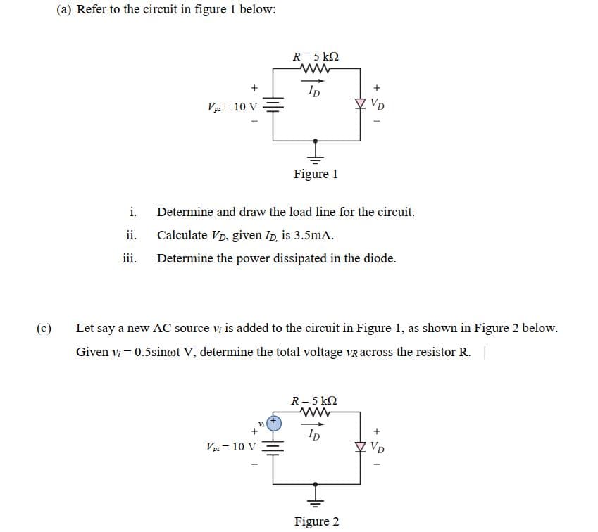
Transcribed Image Text:(a) Refer to the circuit in figure 1 below:
R = 5 k2
Ip
Vp: = 10 V
Figure 1
i.
Determine and draw the load line for the circuit.
ii.
Calculate VD, given Ip, is 3.5mA.
iii.
Determine the power dissipated in the diode.
(c)
Let say a new AC source v is added to the circuit in Figure 1, as shown in Figure 2 below.
Given vi = 0.5sinot V, determine the total voltage vz across the resistor R. |
R = 5 k2
Vp: = 10 V
♡ VD
Figure 2
Expert Solution
This question has been solved!
Explore an expertly crafted, step-by-step solution for a thorough understanding of key concepts.

Step by step
Solved in 4 steps with 3 images

Recommended textbooks for you

Delmar's Standard Textbook Of Electricity
Electrical Engineering
ISBN:
9781337900348
Author:
Stephen L. Herman
Publisher:
Cengage Learning
Delmar's Standard Textbook Of Electricity
Electrical Engineering
ISBN:
9781337900348
Author:
Stephen L. Herman
Publisher:
Cengage Learning