A series R-L-C circuit is fed by a 230 V, 60 Hz ac supply. The circuit elements are R = 2 ohms, L = 53.05 mH and C is unknown. If the total real power taken from the supply is 800 W at a leading power factor, determine the value of C. Select the correct response: 84.7 uF 84.7 F 84.7 mF 8.47 uF
A series R-L-C circuit is fed by a 230 V, 60 Hz ac supply. The circuit elements are R = 2 ohms, L = 53.05 mH and C is unknown. If the total real power taken from the supply is 800 W at a leading power factor, determine the value of C. Select the correct response: 84.7 uF 84.7 F 84.7 mF 8.47 uF

Delmar's Standard Textbook Of Electricity
7th Edition
ISBN:9781337900348
Author:Stephen L. Herman
Publisher:Stephen L. Herman
Chapter23: Resistive-inductive-capacitive Series Circuits
Section: Chapter Questions
Problem 3PP: The circuit is connected to a 60-Hz line. The apparent power in the circuit is 29.985 VA, and the...

Related questions
Question
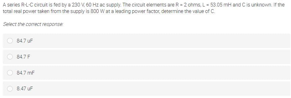
Transcribed Image Text:A series R-L-C circuit is fed by a 230 V, 60 Hz ac supply. The circuit elements are R = 2 ohms, L = 53.05 mH and C is unknown. If the
total real power taken from the supply is 800 W at a leading power factor, determine the value of C.
Select the correct response:
84.7 uF
84.7 F
84.7 mF
8.47 uF
Expert Solution
This question has been solved!
Explore an expertly crafted, step-by-step solution for a thorough understanding of key concepts.

Step by step
Solved in 3 steps with 2 images

Knowledge Booster


Learn more about
Need a deep-dive on the concept behind this application? Look no further. Learn more about this topic, electrical-engineering and related others by exploring similar questions and additional content below.Recommended textbooks for you
Delmar's Standard Textbook Of Electricity
Electrical Engineering
ISBN:
9781337900348
Author:
Stephen L. Herman
Publisher:
Cengage Learning
Delmar's Standard Textbook Of Electricity
Electrical Engineering
ISBN:
9781337900348
Author:
Stephen L. Herman
Publisher:
Cengage Learning