A series RC circuit with R=4k0 and C=0.40µF is connected to an AC voltage source t)=100sin200t. Determine the following: (a) What is the cm.s current in the circuit? (b) What is the phase between the voltage and the current? (c) Find the power dissipated in the circuit. AT
Q: 1) With reference to the circuit diagram given below formulate the condition for the continuous…
A: Given: Consider the circuit diagram: To find: Formulate the condition for the continuous current to…
Q: 1. A series RLC circuit illustrated below is supplied by a 120 Volts, 60 Hz source. The values for…
A:
Q: The following is given for a series R-L-C circuit: resistor (R) = 8 Ohms, an inductor (L) = 32 mH…
A:
Q: O At the value of K where the system is marginally stable, what are the pole locations? 15j, -6 15j,…
A:
Q: 2. A current source in a linear circuit has is = 8cos(500nt – 25°) %3D (a) What is the amplitude of…
A:
Q: Find the current flowing through the RLC circuit connected through an AC source of 240 V as given…
A:
Q: Impedance of AC circuit and Admittance of AC circuit SHOW THE CIRCUIT USING ANY SOFTWARE OR YOU CAN…
A:
Q: Using the phase shift of 72º from the Experiment, determine the inductance value, L, of the inductor…
A:
Q: ELECTRICAL CIRCUIT: Solve the problem and show your complete solution. The maximum values of the…
A:
Q: The capacitor of external defibrillator must be loaded at 1500V, in order to generate a two-phase…
A: CAPACITOR: Any two conducting surfaces separated by an insulating material is called a capacitor od…
Q: Fox the Coupled Circuit shown, find mutual inductance "M" the value of and put the dots on the Coil…
A: Let us assume the coils are connected in cumulative series. Let L be the equivalent inductance of…
Q: The schematic diagram shows a series RLC circuit. To determine: a) The impedance; b) The current; c)…
A: Note: We are authorized to answer three subparts at a time, since you have not mentioned which part…
Q: Short Problem: Given a parallel RLC circuit comprised of the following element: 95.34-ohm resistor,…
A:
Q: Re For the electrode model given in the figure, assume that R= 3000 Ohm, R, 8 Ohm and C 0.1 micro…
A: Given circuit shown Rd=3000 ΩRs=8 ΩCd=0.1 μFEhc=0.223 v
Q: An R-C circuit consisting of a 4.7µF capacitor in series with a 200 2 resistor, is connected to a…
A:
Q: With reference to the source voltage, show the values of v, i, vr, vc in the time plane, the phasor…
A: The impedance for capacitor is written as -jXc where Xc=1ωC and ω=2πf. The total current is the…
Q: Q Find the capacitance C necessary to improve the power factor to 0.95 lagging in the circuit shown…
A:
Q: The voltage across the circuit breaker is given by vV; = Vm (1-cos →), prove tha the maximum…
A: Given expression for voltage across circuit breaker (restriking voltage) , differentiate the…
Q: Find the current flowing through the RLC circuit connected through an AC source of 240 V as given…
A: Given data, V=240 V, R=100 Ω, L=100 mH, C=100 μF, f=50 Hz Given circuit diagram,
Q: A source delivers an AC voltage of the form AV = 198 sin( 51 nt), where AV is in volts and t is in…
A: Here, we have given some information about the voltage delivered by the voltage source. The maximum…
Q: In the AC circuit shown in the figure below, R = 70.0 2 and the output voltage of the AC source is…
A:
Q: The following is given for a series R-L-C circuit: resistor (R) = 8 Ohms, an inductor (L) = 32 mH…
A: A series RLC circuit offers a net impedance of Z. The expression for the Total impedance offered by…
Q: %3D %3D %3D For the circuit shown in the following figure. If Ig = 75 µA, B = 100, Vcc = 15 V, and R…
A: A transistor connected in the common-emitter configuration is given in the question. The input…
Q: The Shunt Capacitance in the Transmission Line produces the Charging Current. Select one: True…
A: Choose the given Statment is true or false The Shunt Capacitance in the Transmission Line produces…
Q: What impedance vector (0- j15) Ohms represents: A. A pure resistance. C. A pure capacitance.…
A: Since real part is 0, so it can't be resistor. So option A is wrong.
Q: Volts 20 10 5 10 15 20 25 30 35 40 45 50 t (ms) -10 - -20 Given the above graph. Which general…
A:
Q: What is the peak current in a AC circuit with a 50 ohm resistor, 3.3 mH inductor, and a 480 nF…
A: This is the series RLC circuit and concept of resonance Use fundamental formulas
Q: A transmission line has a capacitance of 25 pF / ft. and an inductance of 0.15 µh / ft. Determine…
A:
Q: 1.) In a linear circuit, the voltage source is us = 12 sin(10°t+ 24)V (a) What is the angular…
A:
Q: A coil RL is connected in series with a capacitor across the 220 V, 60 hz, AC supply. If this…
A:
Q: determine the inductive reactance of rlc series ac circuit given the ff: rms current=7.5A…
A:
Q: Q1) a). A 1.5 H coil has R of 70 2. The coil is energised by e = 149 sin 314 t. obtain the…
A:
Q: A coil, with 100 mH Of Inductanče and resistance, has been CO UP 01 Da ower supply Vs(t)= 200…
A:
Q: Compute the expected power factor of the circuit given the different capacitance.
A:
Q: Assuming the following parallel as circuit is built: Xc = 60 XL = 3 0 I5 = 102 30°A R1 Xc XL R1 = 80…
A: In this question, in the circuit, a current source connected to RLC parallel circuit. Find the…
Q: Q5) For the waveform shown below, find Vrms v(t) A 2 LAA: 4 6 l10 t -1
A: The given waveform is shown below. Find Vrms.
Q: Find the impedance theoretically of a wire if it carries the frequency 10 kHz have a voltage is 8v,…
A:
Q: Find the current flowing through the RLC circuit connected through an AC source of 240 V as given…
A: Given data, Supply voltage V = 240 V Resistance R=100 Ω Inductance L=100 mH Capacitance C=100 μF…
Q: Problem 5.3 Find the total inductance of the circuit shown.
A:
Q: Find the Thevenin equilvent circuit
A: The circuit diagram is:
Q: 11. A current source in a linear circuit has i, = 15 cos(25 t + 25°) A Find the amplitude, angular…
A: We use the given current equation to find amplitude , time period , frequency and phase angle.
Q: A 200 Ω resistor, 0.900 H inductor, and 6.00 µF capacitor are connected in series across a voltage…
A: The RLC in series connection is shown below.
Q: Suppose that an inductor (L) - resistor (R) – capacitor (C) circuit is connected to an AC source…
A:
Q: Obtain the overall impedance for the following cases a. P= 1500 W, Q = 2000 VAR (inductive), Irms =…
A: Given Data: a) P = 1500 W Q = 2000 VAR Irms = 12 A b) S = 4500 angle 60 VA V = 120 angle 45 V
Q: VR), magnitude of the voltage across inductance (VL) and capacitance (Vc the following RLC series…
A: In this question we will find voltage source value and active power consumption with given data....
Q: A circuit is designed with an AC source of max voltage 12 and frequency 60 Hz. The circuit has a…
A:
Q: When a series RC circuit is connected to a dc voltage, the circuit current reaches 63.2% of it final…
A: In this question we need to check the given statement is true or false
Q: The resistance and inductance of a coil can be obtained by connecting the coil in series with a…
A:
Q: Three currents i,, i, and i, are approaching a node. If i, = 10 sin (400t + 60°) A, and i, = 10 sin…
A: In this question we will find current i 3...
Q: 2) The amplitude of the emf in the below circuit is 150V, while the angular frequency is 60x. The…
A:
6. complete solution
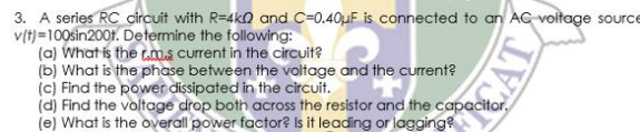
Trending now
This is a popular solution!
Step by step
Solved in 3 steps with 2 images
- A circuit is designed with an AC source of max voltage 12 and frequency 60 Hz. The circuit has a resistance of 1050 Ohms, an inductance of 0.06 Henrys, and a capacitance of 0.009 coulombs per volt. - omega for source in rad/s? - omegaR for circuit? -XL? -XC? -phi in radians? -Z? -imax?A LC circuit in a radio tuned to 1080 kHz has an inductor with an inductance value of 60 μH and a resistance of 0.25 Ω. a. what is the capacitance of the LC circuit? b. sketch the impedance phasor diagram for the radio. Be sure to label important features of the diagram.1. For the following sinusoids, determine which one leads and by how much a. ?(?) = 10cos (4? − 60°) and ?(?) = 6sin (4? + 50°)b. ?ଵ(?) = 4cos (377? + 10°) and ?ଶ(?) = −20cos(377?)c. ?(?) = 13 cos(2?) + 5 sin(2?) and ?(?) = 15cos (2? − 11.8°)
- Ac - 100 VrmsR1 - 1kR2 - 500Rload - 1kCapacitor - 2uF Q1. How much is the capacitor voltage lagging from the AC sourceThe capacitor of external defibrillator must be loaded at 1500V, in order to generate a two-phase wave of 150 J.Considering a transthoracic impedance is 80ohms and a capacitance of 30 000 uF. 3- What is the energy of the capacitor?4- What is the internal impedance of the defibrillator in the previous cases?An RLC series circuit has an impedance of 60 Ω and a power factor of 0.50, with the voltage lagging the current. (a) Should a capacitor or an inductor be placed in series with the elements to raise the power factor of the circuit?(b) What is the value of the capacitance or self-inductance that will raise the power factor to unity?
- What is incorrect about the RLC AC Circuit shown? 1 The power dissipation through the (ideal) capacitor is vanishing. 2 The current leads the voltage across the capacitor by 90deg. 3 The voltage across the inductor leads the current by 90deg. 4 If the AC source is replaced by a constant DC source, after a very longtime, the voltage across the inductor vanishes. 5 If the AC source is replaced by a constant DC source, after a very longtime, the voltage across the capacitor will be equal to that across theresistor.An RLC circuit (has resistance and reactive elements) supplied by a 60Hz power source is found to have a lagging power factor (PF). What can you say about the relative contributions of the resistance (R), XL inductance, XC capacitance & resistance/reactance (ratio) utilized in this circuit at the 60Hz frequency? (min two statements – major reactive element & comparison to Resistive element)A resistor, an inductor, and a capacitor are connected in parallel to an ac source with voltage amplitude V and angular frequency v. Let the source voltage be given by v = Vcosvt. (a) Show that each of the instantaneous voltages vR, vL, and vC at any instant is equal to v and that i = iR + iL + iC, where i is the current through the source and iR, iL, and iC are the currents through the resistor, inductor, and capacitor, respectively. (b) What are the phases of iR, iL, and iC with respect to v? Use current phasors to represent i, iR, iL, and iC. In a phasor diagram, show the phases of these four currents with respect to v. (c) Use the phasor diagram of part (b) to show that the current amplitude I for the current i through the source is I = √(I2R) + (IC - IL)2 . (d) Show that the result of part (c) can be written as I = V/Z, with 1/Z = √ (1/R2) + [ωC - (1/ωL)]2.
- Q5. For an exhibition project you are designing a circuit of signal processor which can be connected to 230V, 50 Hz supply have a 5.0 H inductor, 80 μ F capacitor and 40Ω resistor kept in series. How can you evaluate the rms current and average power delivered to the circuit? Based on your observation, evaluate the potential drop across capacitance and inductor. Comment about that r m s voltage found in this circuit is less than peak voltage? Justify it with your answer. If you remove the inductor and connect a bulb in series with a capacitor. What will happen to the brightness of bulb if it is connected to DC source and then to an AC source. Assess and find reason for your observations in each case.In alternating current, AC, theory, the voltage through an inductor leads the current by a phase angle of 90°. Complex numbers can help in this situation as when a real number is multiplied by i it rotates through 90° on the Argand diagram, with the magnitude remaining the same. This allows us to specify the impedance through an inductor as a complex number. This can be combined with a resistor to give a combined impedance of z = r + Li. If we have two such elements in a circuit, we can use complex numbers to determine the total impedance when they are in series and in parallel. In series Zt = Z1 + Z2 In Parallel Add the following two impedances (a) in series and (b) in parallel. Z1 = 4 + 3i and Z2 = 12 + 5iIn alternating current, AC, theory, the voltage through an inductor leads the current by a phase angle of 90°. Complex numbers can help in this situation as when a real number is multiplied by i it rotates through 90° on the Argand diagram, with the magnitude remaining the same. This allows us to specify the impedance through an inductor as a complex number. This can be combined with a resistor to give a combined impedance of z = r + Li. If we have two such elements in a circuit, we can use complex numbers to determine the total impedance when they are in series and in parallel. In series Zt = Z1 + Z2 In Parallel