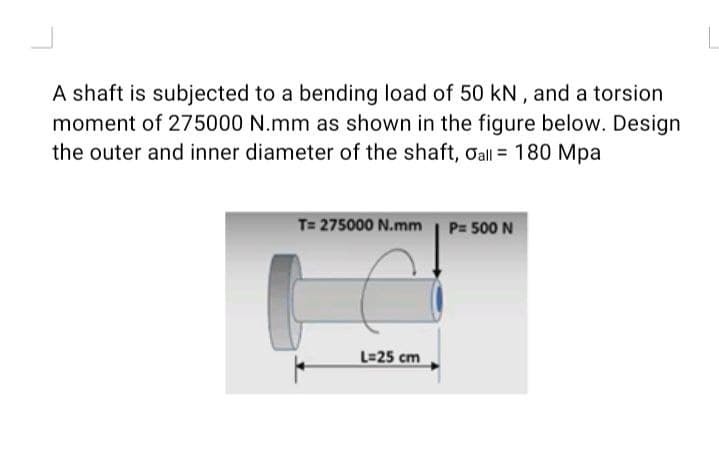
A shaft is subjected to a bending load of 50 kN, and a torsion moment of 275000 N.mm as shown in the figure below. Design the outer and inner diameter of the shaft, Oall = 180 Mpa T= 275000 N.mm P= 500 N L=25 cm


Q: A wire of circular cross-section ofdiameter 1.0 mm is bent into a circular arc of radius 1.0 m by…
A: Given, Diameter of wire = d = 1 mm Circular arc radius = R = 1 m = 1000 mm Young's modulus = E = 100…
Q: A hollow steel shaft used in a constructionauger has an outer diameter d2 = 6.0 in. and…
A: Given d1 = 4.5 in d2 = 6 in G = 11 X 106 psi T = 150 kip-in To find Shear at outer surface Shear at…
Q: A composite beam consists of concrete slab (1) that is rigidly attached to the top flange of a W16 ×…
A:
Q: 3 KN/m D B 120 mm YA= 40 mm A. 80 mm 1m 2 m 10 KN 10 KN L= 4 m
A:
Q: Q/ For the shaft shown in the figure below, find: Maximum torsional stress in part AB, Maximum…
A: as per guidelines i have to solve only three subpart of your question
Q: A 1.750-in.-diameter solid steel shaft supports loads PA = 280 lb, Pc = 510 lb, and PE = 280 lb, as…
A:
Q: A section is under the effect of M (kNm) bending moment which makes 6° with the positive +z axis as…
A:
Q: Solve the number four (iv) only ; (i) The moment of inertia = ii) The radius of curvature is…
A:
Q: A hollow shaft (k = 0.4) is subjected to a bending load of 500 N, and a torsion moment of 275000…
A:
Q: The composite beam in the figure is made of steel and aluminum. Beam In steel and aluminum as it is…
A: Given: Esteel=210GPa Eal=70GPa M=2kNm Solution: The position of the neutral axix is exactly at the…
Q: The distributed load on the T-section beam in the figure is w = 100 kN/m. The tensile stress that…
A: Bending stress in beams When external load acts on beam shear force and bending moment are set up at…
Q: A beam has a bending moment of 4 kN-m applied to a section with a hollow circular cross-section of…
A:
Q: A solid 1.375 in. diameter shaft is subjected to a torque of T = 340 lb ft and an axial load Pacting…
A:
Q: A wire of circular cross-section of diameter 1.0 mm is bent into a circular arc of radius 1.0 m by…
A:
Q: Q2c) The steel alloy shaft having a diameter of 38 mm is used to transmit torque, T as shown in…
A: Given: Solution:
Q: applied to the beam in the figure with the notches below and a hole of diameter d in the middle.…
A:
Q: The maximum bending stress at distance 0.5 m from the built-in right hand end in the structural beam…
A:
Q: A stepped shaft ABC consisting of two solid circular segments is subjected to torques T1 and T2…
A:
Q: The figure shows a rectangular section beam with a distributed load of 3 KN/m. Decide: The maximum…
A: Consider a beam having Area Moment of Inertia I and Young's modulus E is subjected to bending moment…
Q: 4 - An aluminum circular shaft, fixed at both ends, is loaded by torques applied at points B and C,…
A:
Q: 4. M 5 in. |t = 0.25 in. 3.25 in. a) The rectangular tube shown in the figure is obtained from an…
A:
Q: Calculate the maximum internal bending moment in the shaft. Data: shaft diameter d3 50 mm; L=0.2 m;…
A:
Q: A prismatic bar AB of length L and solidcircular cross section (diameter d) is loaded by…
A: Given Diameter = d Length = L Find Maximum shear stress Angle of twist
Q: A vertical shaft is supported by a thrust collar and bearing plate, as shown in Figure. Calculate…
A: given: Dc=150mm Ds=100mm σ=100MPa Maximum axial load between the collar and plate. P=σ×A…
Q: A 1.00 in. diameter solid steel shaft supports loads PA = 75 Ib, Pc = 135 lb, and PE = 50 lb. Assume…
A:
Q: Q/ For the shaft shown in the figure below, find: Maximum torsional stress in part AB, Let E = 200…
A:
Q: For the beam illustrated in the figure, find the locations and magnitudes of the maximum tensile…
A:
Q: 40 N.m Da 0.5 m 280 N.m 150 N.m 2 0.3 m 0.4 m
A:
Q: The hollow shaft shown in the figure below is fixed at one end and has a lever at the other. The…
A:
Q: 1. The nonprismatic cantilever circular bar has an internal cylindrical hole from 0 to x, so that…
A: Given data J1=78IpJ2=Ip (a) ∑Mx=0,Find reaction momentR1+T+T2=0R1+T+T2=0R1=-32T
Q: The maximum bending stress at distance 0.5 m from the built-in right hand end in the structural beam…
A:
Q: A vertical shaft is supported by a thrust collar and bearing plate, as shown in Figure. Calculate…
A:
Q: A steel bar of 0.8 x 2.5-in. rectangular cross section is subjected to two equal and opposite…
A: yield strength = 36 ksi Calculate the value of the bending moment M σ=MYIY=2.52=1.25…
Q: For the simply supported beam in figure, the shear force at midspan equals: 80 kN 80 kN 2 4 m Select…
A: Given, External force = 80 kN
Q: A stepped shaft ABC consisting of two solid circular segments is subjected to torques '1 and T,…
A:
Q: A stepped shaft of solid circular cross sections(see figure) has length L = 0.80 m, diameterd2 = 40…
A: Given Diameter, d1 = 1.0 in. d2 = 1.2 in. Length, L = 45 in.…
Q: A beam has a bending moment of 3.5 kN-m applied to a section with a hollow circular cross-section of…
A: Given The bending moment on the beam is M=3.5 kN·m. The external diameter of circular beam is D=3.5…
Q: A beam has a bending moment of 3 kN-m applied to a section with a hollow circular cross-section of…
A: We are suppose to solve only 3 subparts. Please post other parts as separate question.
Q: Rectangular cross-section and width given the loading state in the figure Bending safety stress of…
A:
Q: Problem 2 For the beam shown in the figure A) Draw the shear-force and bending-moment diagrams for…
A:
Q: A hollow steel shaft used in a construction auger has outer diameter d2 = 7.8 in. and inner…
A: Given data:
Q: 9 A rectangular cross section beam of width 0.25 m and depth 0.4 m is subjected to a bending moment…
A: Calculated distance from the top surface where normal stress will be zero.
Q: A beam has a bending moment of 3.5 kN-m applied to a section with a hollow circular cross-section of…
A:
Q: Let's consider a solid circular rod having a diameter D = 30 mm subjected to a triangular…
A: Given: The diameter of rod, D = 30 mm The elastic modulus, E = 4 GPa The intensity of load…
Q: Rectangular section and width given in the figure The bending safety stress of the beam with b = 150…
A:
Q: A beam has a bending moment of 3.5 kN-m applied to a section with a hollow circular cross-section of…
A: Since you have asked a question with multiple parts in a single request we would be answering only…
Q: A 1.00-in.-diameter solid steel shaft supports loads Pa = 485 lb and PD = 279 lb as shown. Assume L1…
A:
Q: A hollow circular tube having an inside diameter of 10.0 in. and a wall thickness of 1.0 in. (see…
A: Given Torque, T = 1200 kip-in Thickness, t = 1 in Inside Diameter, D = 10 in Outer diameter, d =…
Q: 40 mm 15 mm d-30 mm 20 m
A:
Q: A 1.125-in-diameter solid steel shaft supports loads PA = 270 Ib, Pc = 550 lb, and PE = 270 Ib, as…
A:

Step by step
Solved in 2 steps with 3 images


- A thin-walled aluminum tube of rectangular cross section (sec fig me) has a centerline dimensions b = 6.0 in. and b = 4.0 in. The wall thickness t is constant and equal to 0.25 in. Determine the shear stress in the tube due to a torque T = 15 kip-in. Determine the angle of twist (in degrees) if the length L of the tube is 50 in. and the shear modulus G is 4.0 x 10⁶ psi.A circular aluminum tube subjected to pure torsion by torques T(sec figure) has an outer radius r2equal to 1.5 times the inner radius r1. (a) If the maximum shear strain in the tube is measured as 400 × 10-6 rad, what is the shear strain y1at the inner surface? (b) If the maximum a1lo-abk rate of twist is 0.125 °/m and the maximum shear strain is to be kept at 400 × 10-6 rad by adjusting the torque T, that is the minimum required outer radius ( r2)Min?.17 A mountain-bike rider going uphill applies torque T = Fd(F = l5lb, d = 4 in.) to the end of the handlebars ABCD by pulling on the handlebar extenders DE. Consider the right half of the handlebar assembly only (assume the bars are fixed at the fork at A). Segments AB and CD are prismatic with lengths L, = 2 in.andL3 = 8.5 in, and with outer diameters and thicknesses d01 = 1.25 in. 101 = 0.125 in. and d03 = O.87in.,i03 = 0.ll5in, respectively as shown. Segment BC’ of length L, = 1.2 in. however. is tapered, and outer diameter and thickness vary linearly between dimensions at B and C. Consider torsion effects only. Assume G = 4000 ksi is constant. Derive an integral expression for the angle of twist of half of the handlebar tube when it is subjected to torque T = Fd acting at the end. Evaluate ‘b1-, for the given numerical1ues.
- A plastic-lined steel pipe has the cross-sectional shape shown in the figure. The steel pipe has an outer diameter d1= 100 mm and an inner diameter d2= 94 mm. The plastic liner has an inner diameter d1= 82 mm. The modulus of elasticity of the steel is 75 times the modulus of the plastic. Determine the allowable bending moment Mallowif the allowable stress in the steel is 35 M Pa and in the plastic is 600 kPa. If pipe and liner diameters remain unchanged, what new value of allowable stress for the steel pipe will result in the steel pipe and plastic liner reaching their allowable stress values under the same maximum moment (i.e., a balanced design)? What is the new maximum moment?A propeller shaft for a small yacht is made of a solid steel bar 104 mm in diameter. The allowable stress in shear is 48 MPa, and the allowable rate of twist is 2.0° in 3.5 meters. (a) Assuming that the shear modulus of elasticity is G = 80 GPa, determine the maximum torque that can be applied to the shaft. (b) Repeat part (a) if the shaft is now hollow with an inner diameter of 5d18. Compare values to corresponding values from part (a).A stepped shaft ABC consisting of two solid, circular segments is subjected to uniformly distributed torque t1acting aver segment 1 and concentrated torque t2applied at C, as shown in the figure. Segment 1 of the shaft has a diameter of d1= 57 mm and length of L1= 0.75 m; segment 2 has a diameter d2— 44 mm and length L2= 0.5 m. Torque intensity /,"= 3100 N . m/m and T2= 1100 N. m. (a) Find reaction torque TAat support A. (b) Find the internal torque T(x) at two locations: .x = L1/2 and at .x = L1+ L2/2. Show these internal torques on properly drawn free-body diagrams.
- The stepped shaft shown in the figure is required to transmit 600 kW of power at 400 rpm. The shaft has a full quarter-circular fillet, and the smaller diameter D1= 100 mm. If the allowable shear stress at the stress concentration is 100 MPa, at what diameter will this stress be reached? Is this diameter an upper or a lower limit on the value of D2?A solid circular bar having diameter d is to be replaced by a rectangular tube having cross-sectional dimensions d × 2d to the median line of the cross section (see figure). Determine the required thickness tminof the tube so that the maximum shear stress in the tube will not exceed the maximum shear stress in the solid bar.A long, thin-walled tapered tube AB with a circular cross section (see figure) is subjected to a torque T. The tube has length L and constant wall thickness t. The diameter to the median lines of the cross sections at the ends A and B are dAand dB, respectively. Derive the following formula for the angle of twist of the tube: Hint: If the angle of taper is small, you may obtain approximate results by applying the formulas for a thin-walled prismatic tube to a differential element of the tapered tube and then integrating along the axis of the tube.
- A stepped shaft of solid circular cross sections (see figure) has length L = 45 in., diameter d2=1.2 in., and diameter d1= 1.0 in. The material is brass with G = 5.6 × 10⁶ psi. Determine the strain energy U of the shaft if the angle of twist is 3.0°.A stepped shaft of solid circular cross sections (see figure) has length L = 0.80 m, diameter d2= 40 mm, and diameter d2= 30 mm. The material is steel with G = 80 GPa. Determine the strain energy U of the shaft if the angle of twist is 1.0º.A tubular bar with outside diameterd2= 4.0 in, is twisted by torques T = 70,0 kip-in. (see figure). Under the action of these torques, the maximum tensile stress in the bar is found to be 6400 psi. Determine the inside diameter rtf of the bar. If the bar has length L = 48.0 in. and is made of aluminum with shear modulus G = 4,0 × 10⁶ psi, what is the angle of twist d (in degrees) between the ends of the bar? (c) Determine the maximum shear strain y (in radians)?