A signal propagation in a waveguide has a full wave of electric intensity change between the two further walls, and no component of the electric field in the * direction of propagation. The mode is TE20 O All mentioned TM11 O TE10 TE01 None of mentioned
A signal propagation in a waveguide has a full wave of electric intensity change between the two further walls, and no component of the electric field in the * direction of propagation. The mode is TE20 O All mentioned TM11 O TE10 TE01 None of mentioned

Introductory Circuit Analysis (13th Edition)
13th Edition
ISBN:9780133923605
Author:Robert L. Boylestad
Publisher:Robert L. Boylestad
Chapter1: Introduction
Section: Chapter Questions
Problem 1P: Visit your local library (at school or home) and describe the extent to which it provides literature...

Related questions
Question
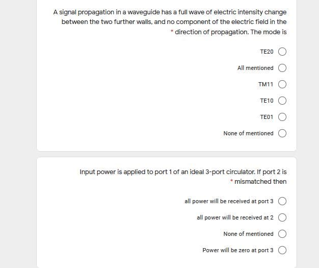
Transcribed Image Text:A signal propagation in a waveguide has a full wave of electric intensity change
between the two further walls, and no component of the electric field in the
* direction of propagation. The mode is
TE20 O
All mentioned
TM11 O
TE10 O
TE01
None of mentioned
Input power is applied to port 1 of an ideal 3-port circulator. If port 2 is
* mismatched then
all power will be received at port 3 O
all power will be received at 2 O
None of mentioned
Power will be zero at port 3 O
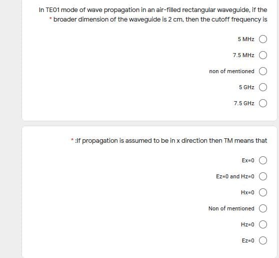
Transcribed Image Text:In TE01 mode of wave propagation in an air-filled rectangular waveguide, if the
* broader dimension of the waveguide is 2 cm, then the cutoff frequency is
5 MHz
7.5 MHz
non of mentioned
5 GHz
7.5 GHz
:If propagation is assumed to be in x direction then TM means that
Ex=0
Ez=0 and Hz=0
Hx=0
Non of mentioned
Hz=0
Ez=0
Expert Solution
This question has been solved!
Explore an expertly crafted, step-by-step solution for a thorough understanding of key concepts.

Step by step
Solved in 2 steps with 1 images

Knowledge Booster


Learn more about
Need a deep-dive on the concept behind this application? Look no further. Learn more about this topic, electrical-engineering and related others by exploring similar questions and additional content below.Recommended textbooks for you
Introductory Circuit Analysis (13th Edition)
Electrical Engineering
ISBN:
9780133923605
Author:
Robert L. Boylestad
Publisher:
PEARSON

Delmar's Standard Textbook Of Electricity
Electrical Engineering
ISBN:
9781337900348
Author:
Stephen L. Herman
Publisher:
Cengage Learning

Programmable Logic Controllers
Electrical Engineering
ISBN:
9780073373843
Author:
Frank D. Petruzella
Publisher:
McGraw-Hill Education
Introductory Circuit Analysis (13th Edition)
Electrical Engineering
ISBN:
9780133923605
Author:
Robert L. Boylestad
Publisher:
PEARSON
Delmar's Standard Textbook Of Electricity
Electrical Engineering
ISBN:
9781337900348
Author:
Stephen L. Herman
Publisher:
Cengage Learning
Programmable Logic Controllers
Electrical Engineering
ISBN:
9780073373843
Author:
Frank D. Petruzella
Publisher:
McGraw-Hill Education

Fundamentals of Electric Circuits
Electrical Engineering
ISBN:
9780078028229
Author:
Charles K Alexander, Matthew Sadiku
Publisher:
McGraw-Hill Education

Electric Circuits. (11th Edition)
Electrical Engineering
ISBN:
9780134746968
Author:
James W. Nilsson, Susan Riedel
Publisher:
PEARSON

Engineering Electromagnetics
Electrical Engineering
ISBN:
9780078028151
Author:
Hayt, William H. (william Hart), Jr, BUCK, John A.
Publisher:
Mcgraw-hill Education,