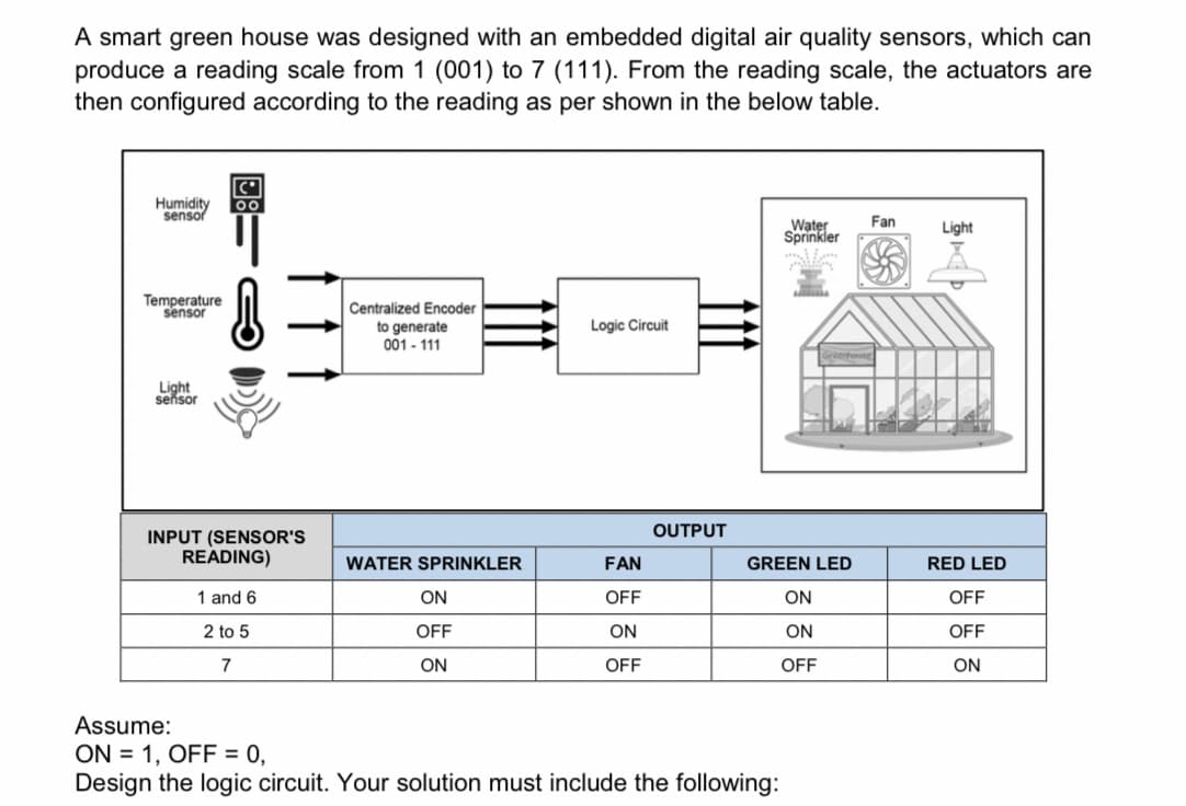
A smart green house was designed with an embedded digital air quality sensors, which can produce a reading scale from 1 (001) to 7 (111). From the reading scale, the actuators are then configured according to the reading as per shown in the below table. Humidity sensor 00 Fan Water Sprinkler Light Temperature sensor Centralized Encoder to generate 001 - 111 Logic Circuit Light sensor OUTPUT INPUT (SENSOR'S READING) WATER SPRINKLER FAN GREEN LED RED LED 1 and 6 ON OFF ON OFF 2 to 5 OFF ON ON OFF 7 ON OFF OFF ON Assume: ON = 1, OFF = 0, Design the logic circuit. Your solution must include the following:
A smart green house was designed with an embedded digital air quality sensors, which can produce a reading scale from 1 (001) to 7 (111). From the reading scale, the actuators are then configured according to the reading as per shown in the below table. Humidity sensor 00 Fan Water Sprinkler Light Temperature sensor Centralized Encoder to generate 001 - 111 Logic Circuit Light sensor OUTPUT INPUT (SENSOR'S READING) WATER SPRINKLER FAN GREEN LED RED LED 1 and 6 ON OFF ON OFF 2 to 5 OFF ON ON OFF 7 ON OFF OFF ON Assume: ON = 1, OFF = 0, Design the logic circuit. Your solution must include the following:

Power System Analysis and Design (MindTap Course List)
6th Edition
ISBN:9781305632134
Author:J. Duncan Glover, Thomas Overbye, Mulukutla S. Sarma
Publisher:J. Duncan Glover, Thomas Overbye, Mulukutla S. Sarma
Chapter6: Power Flows
Section: Chapter Questions
Problem 6.39P

Related questions
Question
Transcribed Image Text:A smart green house was designed with an embedded digital air quality sensors, which can
produce a reading scale from 1 (001) to 7 (111). From the reading scale, the actuators are
then configured according to the reading as per shown in the below table.
Humidity
sensor
Water
Sprinkler
Fan
Light
Temperature
sensor
Centralized Encoder
Logic Circuit
to generate
001 - 111
Light
seňsor
OUTPUT
INPUT (SENSOR'S
READING)
WATER SPRINKLER
FAN
GREEN LED
RED LED
1 and 6
ON
OFF
ON
OFF
2 to 5
OFF
ON
ON
OFF
7
ON
OFF
OFF
ON
Assume:
ON = 1, OFF = 0,
Design the logic circuit. Your solution must include the following:

Transcribed Image Text:a) Truth table
b) Karnaugh map and the simplified expression.
c) Logic circuit.
Expert Solution
This question has been solved!
Explore an expertly crafted, step-by-step solution for a thorough understanding of key concepts.

Step by step
Solved in 3 steps with 3 images

Knowledge Booster


Learn more about
Need a deep-dive on the concept behind this application? Look no further. Learn more about this topic, electrical-engineering and related others by exploring similar questions and additional content below.Recommended textbooks for you
Power System Analysis and Design (MindTap Course …
Electrical Engineering
ISBN:
9781305632134
Author:
J. Duncan Glover, Thomas Overbye, Mulukutla S. Sarma
Publisher:
Cengage Learning
Power System Analysis and Design (MindTap Course …
Electrical Engineering
ISBN:
9781305632134
Author:
J. Duncan Glover, Thomas Overbye, Mulukutla S. Sarma
Publisher:
Cengage Learning