A stepped shaft ACB shown in Figure Q2 having solid circular cross sections with two different diameters is held against rotation at the ends. The parameter of X and Y are given in Table Q2. (i) By drawing the free-body diagram of the shaft, write the equation of moment nquilibrium ond ompatibilitu equation for the schoft
A stepped shaft ACB shown in Figure Q2 having solid circular cross sections with two different diameters is held against rotation at the ends. The parameter of X and Y are given in Table Q2. (i) By drawing the free-body diagram of the shaft, write the equation of moment nquilibrium ond ompatibilitu equation for the schoft

Mechanics of Materials (MindTap Course List)
9th Edition
ISBN:9781337093347
Author:Barry J. Goodno, James M. Gere
Publisher:Barry J. Goodno, James M. Gere
Chapter3: Torsion
Section: Chapter Questions
Problem 3.8.7P: A stepped shaft ACE is held against rotation at ends A and B and subjected to a torque T0acting at...

Related questions
Question
Transcribed Image Text:Q2
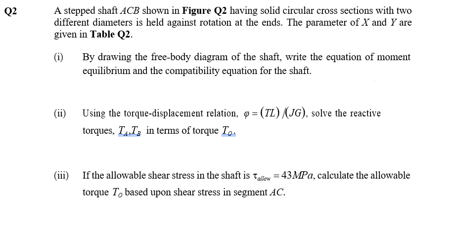
A stepped shaft ACB shown in Figure Q2 having solid circular cross sections with two
different diameters is held against rotation at the ends. The parameter of X and Y are
given in Table Q2.
(i)
By drawing the free-body diagram of the shaft, write the equation of moment
equilibrium and the compatibility equation for the shaft.
(ii)
Using the torque-displacement relation, q= (TL) /(JG), solve the reactive
torques, TT, in terms of torque To.
(iii) If the allowable shear stress in the shaft is allow = 43MPa, calculate the allowable
torque To based upon shear stress in segment AC.
Transcribed Image Text:Parameter
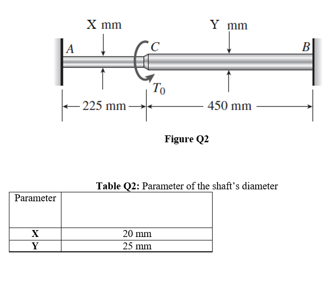
X
Y
X mm
Y mm
225 mm
450 mm
Figure Q2
Table Q2: Parameter of the shaft's diameter
20 mm
25 mm
A
|--2
To
B
Expert Solution
This question has been solved!
Explore an expertly crafted, step-by-step solution for a thorough understanding of key concepts.

Step by step
Solved in 6 steps with 1 images

Knowledge Booster


Learn more about
Need a deep-dive on the concept behind this application? Look no further. Learn more about this topic, mechanical-engineering and related others by exploring similar questions and additional content below.Recommended textbooks for you
Mechanics of Materials (MindTap Course List)
Mechanical Engineering
ISBN:
9781337093347
Author:
Barry J. Goodno, James M. Gere
Publisher:
Cengage Learning
Mechanics of Materials (MindTap Course List)
Mechanical Engineering
ISBN:
9781337093347
Author:
Barry J. Goodno, James M. Gere
Publisher:
Cengage Learning