a) The slip, and rotor mechanical and electrical speeds b) The stator and rotor currents c) The mechanical power and torque
a) The slip, and rotor mechanical and electrical speeds b) The stator and rotor currents c) The mechanical power and torque

Power System Analysis and Design (MindTap Course List)
6th Edition
ISBN:9781305632134
Author:J. Duncan Glover, Thomas Overbye, Mulukutla S. Sarma
Publisher:J. Duncan Glover, Thomas Overbye, Mulukutla S. Sarma
Chapter11: Transient Stability
Section: Chapter Questions
Problem 11.3P

Related questions

Question
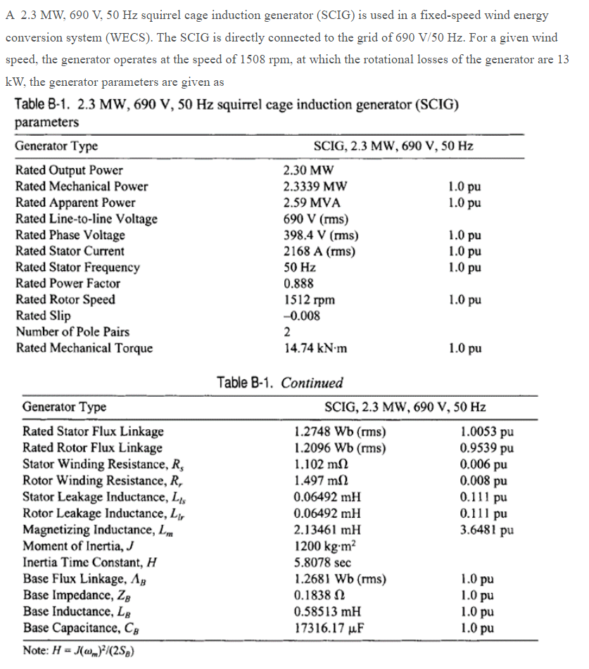
Transcribed Image Text:A 2.3 MW, 690 V, 50 Hz squirrel cage induction generator (SCIG) is used in a fixed-speed wind energy
conversion system (WECS). The SCIG is directly connected to the grid of 690 V/50 Hz. For a given wind
speed, the generator operates at the speed of 1508 rpm, at which the rotational losses of the generator are 13
kW, the generator parameters are given as
Table B-1. 2.3 MW, 690 V, 50 Hz squirrel cage induction generator (SCIG)
parameters
Generator Type
SCIG, 2.3 MW, 690 V, 50 Hz
Rated Output Power
Rated Mechanical Power
2.30 MW
2.3339 MW
1.0 pu
1.0 pu
Rated Apparent Power
Rated Line-to-line Voltage
Rated Phase Voltage
Rated Stator Current
2.59 MVA
690 V (rms)
398.4 V (rms)
2168 A (rms)
1.0 pu
1.0 pu
1.0 pu
Rated Stator Frequency
50 Hz
Rated Power Factor
0.888
Rated Rotor Speed
Rated Slip
1512 rpm
1.0 pu
-0.008
Number of Pole Pairs
2
Rated Mechanical Torque
14.74 kN-m
1.0 pu
Table B-1. Continued
Generator Type
SCIG, 2.3 MW, 690 V, 50 Hz
Rated Stator Flux Linkage
Rated Rotor Flux Linkage
Stator Winding Resistance, R,
Rotor Winding Resistance, R,
Stator Leakage Inductance, L,
Rotor Leakage Inductance, L,
Magnetizing Inductance, Lm
Moment of Inertia, J
Inertia Time Constant, H
Base Flux Linkage, Ag
Base Impedance, ZB
Base Inductance, Lâ
Base Capacitance, Câ
1.2748 Wb (rms)
1.2096 Wb (rms)
1.102 mN
1.0053 pu
0.9539 pu
0.006 pu
0.008 pu
1.497 m2
0.06492 mH
0.111 pu
0.111 pu
3.6481 pu
0.06492 mH
2.13461 mH
1200 kg-m²
5.8078 sec
1.2681 Wb (rms)
0.1838 N
1.0 pu
1.0 pu
1.0 pu
1.0 pu
0.58513 mH
17316.17 µF
Note: H = J(„}/(2Sg)
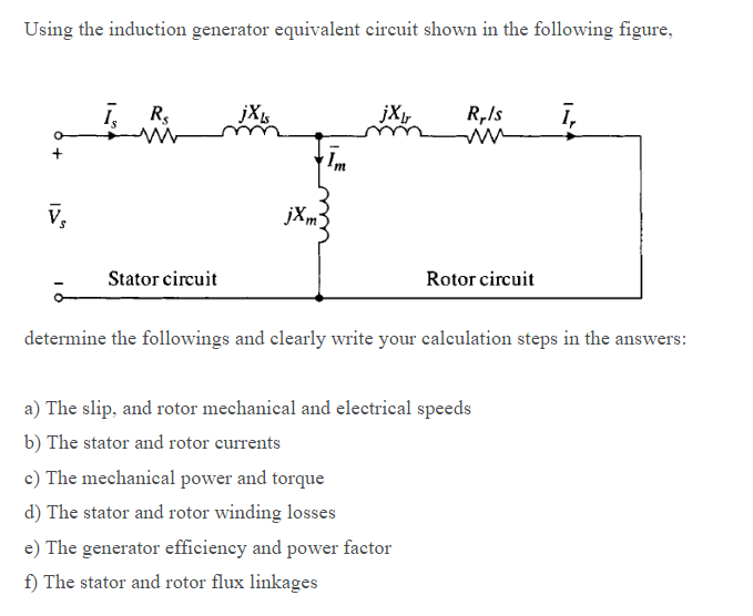
Transcribed Image Text:Using the induction generator equivalent circuit shown in the following figure,
ī, R,
jXr
R,Is
ī,
Im
v,
jXm3
Stator circuit
Rotor circuit
determine the followings and elearly write your calculation steps in the answers:
a) The slip, and rotor mechanical and electrical speeds
b) The stator and rotor currents
c) The mechanical power and torque
d) The stator and rotor winding losses
e) The generator efficiency and power factor
f) The stator and rotor flux linkages
Expert Solution
This question has been solved!
Explore an expertly crafted, step-by-step solution for a thorough understanding of key concepts.

Step by step
Solved in 2 steps

Knowledge Booster


Learn more about
Need a deep-dive on the concept behind this application? Look no further. Learn more about this topic, electrical-engineering and related others by exploring similar questions and additional content below.Recommended textbooks for you
Power System Analysis and Design (MindTap Course …
Electrical Engineering
ISBN:
9781305632134
Author:
J. Duncan Glover, Thomas Overbye, Mulukutla S. Sarma
Publisher:
Cengage Learning

Delmar's Standard Textbook Of Electricity
Electrical Engineering
ISBN:
9781337900348
Author:
Stephen L. Herman
Publisher:
Cengage Learning
Power System Analysis and Design (MindTap Course …
Electrical Engineering
ISBN:
9781305632134
Author:
J. Duncan Glover, Thomas Overbye, Mulukutla S. Sarma
Publisher:
Cengage Learning
Delmar's Standard Textbook Of Electricity
Electrical Engineering
ISBN:
9781337900348
Author:
Stephen L. Herman
Publisher:
Cengage Learning