a- The torque T b- Reactions RA and Rc c- Draw th Bending Diagram

Mechanics of Materials (MindTap Course List)
9th Edition
ISBN:9781337093347
Author:Barry J. Goodno, James M. Gere
Publisher:Barry J. Goodno, James M. Gere
Chapter11: Columns
Section: Chapter Questions
Problem 11.2.15P: Repeat Problem 11.2-14 using L = 12 ft, ß = 0.25 kips/in., ßRl= 1.5ßL2, and ßR2= 2 ßR1.

Related questions

Question
100%
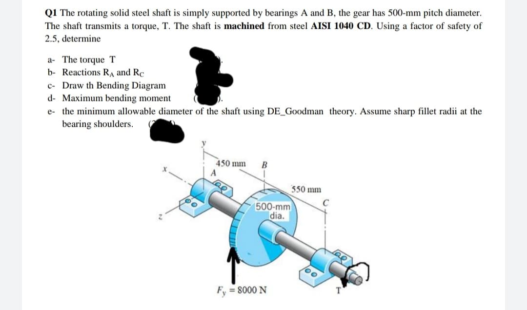
Transcribed Image Text:Q1 The rotating solid steel shaft is simply supported by bearings A and B, the gear has 500-mm pitch diameter.
The shaft transmits a torque, T. The shaft is machined from steel AISI 1040 CD. Using a factor of safety of
2.5, determine
a- The torque T
b- Reactions RA and Rc
c- Draw th Bending Diagram
d- Maximum bending moment
e- the minimum allowable diameter of the shaft using DE_Goodman theory. Assume sharp fillet radii at the
bearing shoulders.
450 mm
B
550 mm
C
500-mm
dia.
Fy = 8000 N
Expert Solution
This question has been solved!
Explore an expertly crafted, step-by-step solution for a thorough understanding of key concepts.

Step by step
Solved in 3 steps with 1 images

Knowledge Booster


Learn more about
Need a deep-dive on the concept behind this application? Look no further. Learn more about this topic, mechanical-engineering and related others by exploring similar questions and additional content below.Recommended textbooks for you
Mechanics of Materials (MindTap Course List)
Mechanical Engineering
ISBN:
9781337093347
Author:
Barry J. Goodno, James M. Gere
Publisher:
Cengage Learning
Mechanics of Materials (MindTap Course List)
Mechanical Engineering
ISBN:
9781337093347
Author:
Barry J. Goodno, James M. Gere
Publisher:
Cengage Learning