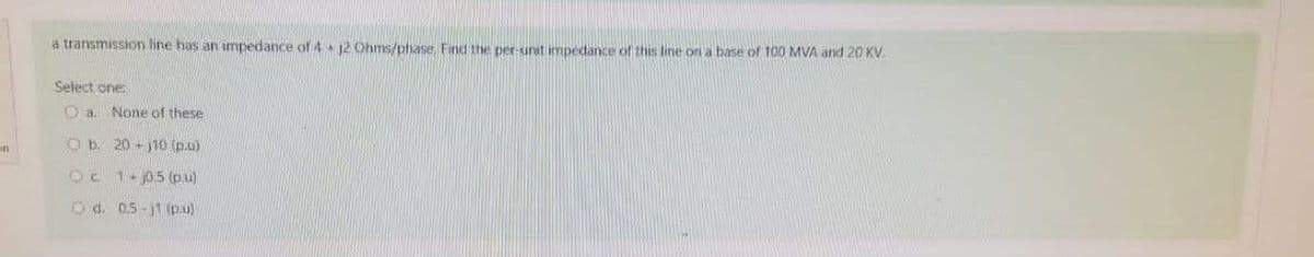
a transmission line has an impedance of 4 12 Ohms/phase, Find the per-unit impedance of this line on a base of 100 MVA and 20 KV Select one: None of these Oa. Ob. 20-j10 (p.u) Oc 1-0.5 (p.u) O d. 0.5-j1 (p.u)
Q: Determine the transfer function C(s)/R(s) using mason's rule. R(s) 10 10 s+12 0.2s 20 C(s)
A:
Q: 36V (b) Find v1 v2 v3 v4 150 402 V₂ Va w 50 792
A:
Q: please solve this a , b , c ,d ...
A: Transformer is a static device which is used to step up or down the voltage level or current…
Q: Explain in paragraph the relationships of resistance, voltage and current, and the distribution of…
A:
Q: Determine the Boolean algebra's of the following logic circuits: A B I
A: Given, The logic circuit,
Q: 5. For the system shown in Figure 3, find the sensitivity of the steady- state error with respect to…
A: Steady state error:- It is the difference between desired value and actual value when response…
Q: The following AC power source connected to two impedances and one resistive load. Analyze the…
A: The Given circuit is To analyze the circuit reactive components and reactive power developed…
Q: Table 5-1. Description Measured Computed E-Audio Generator Output voltage 10Vpp 10 Vpp ER Voltage…
A: Capacitive reactance inversely porotional to frequency Inductive reactance directly proportional to…
Q: A system is described by the differential equation below d²y(t) 5dy(t) dt dx(t) +8y(t) = -+ 7x(t).…
A: given here a differential equation and asked to find the system response.
Q: Calculate the specific capacitance
A: Capacitor- It is one of the passive elements which can't act like source it can only utilize…
Q: Find the voltages V1 and V2 for the circuit shown in the figure P2.24 by combining resistances in…
A: The required parameters can be calculated by reducing the series and parallel connected resistors…
Q: Find the efficincy for short
A: Insulator in transmission line- The device used to protect transmission line and prevent the…
Q: Find V4 by using Superposition theorem R₁ R₁ Ron E₁12 V 3012 R. 1 +11 1241 E
A:
Q: 1- Obtain transfer functions Y(s)/R(s) and Y(s)/N(s) of the system shown
A:
Q: Question Realize f(a,b,c,d) = 210./24 6. 7./6. 7/ 11. f3. 1 other gate far 14, 15) with a 4:1…
A: NOTE: as per our company guidelines we are supposed to answer only one question . kindly re-post…
Q: Find V. for the circuit given below. 9+Vcc -Voc R₂ 9+ Voc A₁
A:
Q: Using the values of the magnitudes given in the image, the injection efficiency of electrons is D₁…
A: Electron injection process is used for injecting transfer of electron from a excited state to an…
Q: Consider the circuit below. The expressions of the outputs(YO, Y1, Y2, Y3) are: 0 XI B A A BO X2 2X4…
A: Multiplier Takes Multiplier inputs and gives one output based on select line Example 2×1,…
Q: A 4 pole lap connected shunt generator has 300 armature conductors and flux per pole of 0.1 wb. It…
A: Given data : poles of generator P=4 Armature conductors Z=300 Flux per pole ϕ=0.1wb Speed of…
Q: a: considering the unity feedback system of fig. ,prove the settling time of the resulting second…
A:
Q: amount. Example 10.4 A direct-FM transmitter has a varactor modulator with k+ = 2 kHz/V and a…
A: "Since you have posted a question with multiple sub-parts, we will solve first three subparts for…
Q: 492 and 1=0 Q1 of 2) The switch has been closed for a long time. It opens at t=0. i) Find i, (0+)…
A: You have asked multiple independent questions Q1 of 2 and Q 1 b. We are authorized to answer one…
Q: At t = 0, the switch is opened after being closed for a very long time. Use the Laplace method. Use…
A: For the above given question we need to calculate the value of initial voltage and current on the…
Q: 27. Sketch sin(377t + 60°) with the abscissa a. angle in degrees. b. angle in radians. c. time in…
A: Since you have asked multiple questions we will solve the first question for you. If you want any…
Q: A circuit is shown in Figure 2 below. The diodes are germanium type with forward biased voltage of…
A:
Q: 4. The portion of the flux that goes through one of the transformer coils but not the other one is…
A: We are authorized to answer three subparts at a time, since you have not mentioned which part you…
Q: 23) Design a perceptron neural network to distinguish patterns between bananas nd pineapples, based…
A: In this chapter we have designed three different neural networks to distinguish between apples and…
Q: 3. For the circuit in Figure 3, find the mathematical expressions for ic (t) and vc (t) in the…
A: Transient response:
Q: sing boolean laws (A.A').(B+C.D)
A:
Q: H.W: Consider about a washing machine equipped with fuzzy logic controller. There are two inputs…
A: Given,The weight of the cloths to be washed is,W=4.5 kgThe cloths are in level 3 of greasiness.
Q: B. Determine the phase angles by which between vl(t) and i1(t), then draw both signals in time and…
A: Given: v1t=4sin377t+25°v1t=0.5cos377t-20°
Q: Find the value of Rf necessary to produce an output that is 10 times the sum of the inputs in the…
A:
Q: the following series circuit, find the equivalent resistance and voltage across each resistance.…
A:
Q: Q2: A. For the figure shown below: A(2,0,0), B(2,1/2,0) C (2,1/2,8),D(1,0°,8).Calculate (a)The…
A:
Q: 21: Assume that V is a function of y and at y=2, V-5 volt and at y = 4, V = 10 volt. a) Fi cis. 30μc…
A: Electric field is also known as electric strength and electric intensity. Electric field is the…
Q: EX2: infinite line along the z-axis with 20 nc/m. Calculate the capacitance between p=10 and p=4 for…
A:
Q: Construct the magnitude and phase plot for the following transfer functions 100(s +20) H(s) = s(s+…
A: By observing se can se that the system is single input single output. The order of the system can be…
Q: Consider the circuit on the left with two resistors, a capacitor and an ideal OP-AMP. You may make…
A: The Given Ideal OP-AMP circuit is
Q: 1. As described in the introduction of this experiment, a common application of series circuits is…
A:
Q: , find the current I and the voltage VAB.
A:
Q: 2. In the circuit shown, R = 55 22, L = 8 mH, and C = 1 µF, if Es = 20 V @ 3 Khz find the : IR Ic Es…
A: NOTE: As per our company guidelines we are supposed to answer only first three sub parts. kindly…
Q: 1. Explain the difference between digital and analogue electronics devices, and then Explain the…
A: Digital devices:- In digital devices signals are discrete in time and values. Signals are…
Q: 1ΜΩ + 18 V + VGSO ΜΑΞΙ 154 IDss = 10 mA 16 Vp = -4V OV 1516 1.5 ΚΩ 100 750 Ω
A: Self-bias FET: It is a voltage-controlled device. in this device, there is no current and 0 voltage…
Q: . For the rotational shown below,Find the transfer function G
A:
Q: SECTION 13.2 Sinusoidal ac Voltage Characteristics and Definitions 1. For the periodic waveform of…
A:
Q: 3. Determine the following parameters below and draw the DC load line. a. Ic +20 V b. IE C. VCE d.…
A: According to the bartleby's guidelines we have to solve only one question posted by students so…
Q: of figure below. Using the principle of superposition, determine the power dissipated in the 4-…
A:
Q: b) The forward path transfer function of a 2 G(S): S(S+3) unity-feedback control system is given by…
A:
Q: Question (1) (a) Define homo-structure and hetero-structure devices with appropriate schematic…
A: “Since you have asked multiple questions, we will solve the first question for you. If you want any…
Q: B. In cylindrical conductor of radius 2 mm, the current density varies with distance from the axis…
A:
Step by step
Solved in 3 steps with 3 images
- A balanced -connected impedance load with (12+j9) per phase is supplied by a balanced three-phase 60-Hz,208-V source, (a) Calculate the line current, the total real and reactive power absorbed by the load, the load power factor, and the apparent load power, (b) Sketch a phasor diagram showing the line currents, the line-to-line source voltages, and the -load currents. Use Vab as the reference.A three-phase line, which has an impedance of (2+j4) per phase, feeds two balanced three-phase loads that are connected in parallel. One of the loads is Y-connected with an impedance of (30+j40) per phase, and the other is -connected with an impedance of (60j45) per phase. The line is energized at the sending end from a 60-Hz, three-phase, balanced voltage source of 1203V (rms. line-to-line). Determine (a) the current, real power. and reactive power delivered by the sending-end source: (b) the line-to-line voltage at the load: (C) the current per phase in each load: and (d) the total three-phase real and reactive powers absorbed by each load and by the line. Check that the total three- phase complex power delivered by the source equals the total three-phase power absorbed by the line and loads.In a balanced three-phase Y-connected system with a positive-sequence source, the line-to-line voltages are 3 times the line-to-neutral voltages and lend by 30. (a) True (b) False
- One advantage of balanced three-phase systems over separate singlephase systems is reduced capital and operating costs of transmission and distribution. (a) True (b) FalseThe instantaneous power absorbed by the load in a single-phase ac circuit, for a general R LC load under sinusoidal-steady-state excitation. is (a) Nonzero constant (b) Zero (c) Containing double-frequency componentsA small manufacturing plant is located 2 km down a transmission line, which has a series reactance of 0.5/km. The line resistance is negligible. The line voltage at the plant is 4800V(rms). and the plant consumes 120kW at 0.85 power factor lagging. Determine the voltage and power factor at the sending end of the transmission line by using (a) a complex power approach and (b) a circuit analysis approach.
- Let a series RLC network be connected to a source voltage V, drawing a current I. (a) In terms of the load impedance Z=ZZ, find expressions for P and Q, from complex power considerations. (b) Express p(t) in terms of P and Q, by choosing i(t)=2Icost. (c) For the case of Z=R+jL+1/jC, interpret the result of part (b) in terms of P,QL, and Qc. In particular, if 2LC=1, when the inductive and capacitive reactances cancel, comment on what happens.consider a transmission line with zl=3.346+j77.299 ohm assume that sb=100mva and vb=735kv find the per unit impedance convert the impedance using a new base of 200 mva and 345 kva short three phase transmission line connected to 33kv 50 hertz generating station at starting and is required to supply a load of 10 MW at pointed start lagging power factor at 30 KV addresses in that is the minimum transmission efficiency is to be determined96% estimate the per face value of resistance and inductance of a line
- Using a test equipment, Vmax was found to be 5V while Vmin is 1V. The distance between voltage maximas is 14 cm and the first maximum was found to be 7 cm from the load. What is the load impedance if the characteristic impedance of the line is 75 ohms?The impedance per phase of 3-phase transmission line on a base of 100 MVA, 100 kV is 2 pu. Find the value of this impedance on a base of 400 MVA and 400 kV would be..A single-phase transmission line has a resistance of 0.22 ohm and inductive reactance of 0.36 ohm. Find the voltage at the sending end to give 500kva at 2000V at the receiving end at a load power factor of 0.707 lagging. Also find the efficiency of transmission at this load.