A typical power system network with two generators G₁ and G2 supplies power to an aggregate motor load (M) is shown in Figure Q3. Rating of equipment and their respective sequence reactance are indicated in the diagram. Use G₁ rating as a base. a) For a fault on bus 4, analyze the network configuration for the Thevenin's equivalent positive, negative, and zero sequence impedances. b) Assess the fault current and fault level when a single line-to-ground fault occurred in the transmission line at bus 4. 60 MVA 3 Overhead line, L₁ X₁ X₂ = X₁ = 0.10 pu on 60 MVA 4 13.8 kV X₁ = 0.08 G₁ T₁ 2 X₂ = 0.08 Xo = 0.05 MY 50 MVA 13.8 kV X₁ = 0.06 ΔΥ Overhead line, L2 X = Xz = Xo = 0.10 pu on 60 MVA X₂ = 0.06 125 MVA 13.8/120 kV X = 0.12 Xo = 0.04 G₂ Figure Q3 T₂ 38 YA 125 MVA 120/13.8 kV X = 0.12 75 MVA 13.8 kV X₁ = 0.10 X₂ = 0.10 Xo = 0.06
A typical power system network with two generators G₁ and G2 supplies power to an aggregate motor load (M) is shown in Figure Q3. Rating of equipment and their respective sequence reactance are indicated in the diagram. Use G₁ rating as a base. a) For a fault on bus 4, analyze the network configuration for the Thevenin's equivalent positive, negative, and zero sequence impedances. b) Assess the fault current and fault level when a single line-to-ground fault occurred in the transmission line at bus 4. 60 MVA 3 Overhead line, L₁ X₁ X₂ = X₁ = 0.10 pu on 60 MVA 4 13.8 kV X₁ = 0.08 G₁ T₁ 2 X₂ = 0.08 Xo = 0.05 MY 50 MVA 13.8 kV X₁ = 0.06 ΔΥ Overhead line, L2 X = Xz = Xo = 0.10 pu on 60 MVA X₂ = 0.06 125 MVA 13.8/120 kV X = 0.12 Xo = 0.04 G₂ Figure Q3 T₂ 38 YA 125 MVA 120/13.8 kV X = 0.12 75 MVA 13.8 kV X₁ = 0.10 X₂ = 0.10 Xo = 0.06

Power System Analysis and Design (MindTap Course List)
6th Edition
ISBN:9781305632134
Author:J. Duncan Glover, Thomas Overbye, Mulukutla S. Sarma
Publisher:J. Duncan Glover, Thomas Overbye, Mulukutla S. Sarma
Chapter9: Unsymmetrical Faults
Section: Chapter Questions
Problem 9.35P

Related questions

Question
Please answer correctly and completely. As soon as possible. Round off final answers into 4 decimal places.
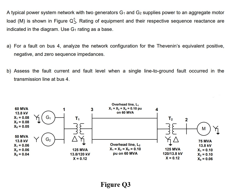
Transcribed Image Text:A typical power system network with two generators G₁ and G2 supplies power to an aggregate motor
load (M) is shown in Figure Q3. Rating of equipment and their respective sequence reactance are
indicated in the diagram. Use G₁ rating as a base.
a) For a fault on bus 4, analyze the network configuration for the Thevenin's equivalent positive,
negative, and zero sequence impedances.
b) Assess the fault current and fault level when a single line-to-ground fault occurred in the
transmission line at bus 4.
60 MVA
3
Overhead line, L₁
X₁ X₂ = X₁ = 0.10 pu
on 60 MVA
4
13.8 kV
X₁ = 0.08
G₁
T₁
2
X₂ = 0.08
Xo = 0.05
MY
50 MVA
13.8 kV
X₁ = 0.06
ΔΥ
Overhead line, L2
X = Xz = Xo = 0.10
pu on 60 MVA
X₂ = 0.06
125 MVA
13.8/120 kV
X = 0.12
Xo = 0.04
G₂
Figure Q3
T₂
38
YA
125 MVA
120/13.8 kV
X = 0.12
75 MVA
13.8 kV
X₁ = 0.10
X₂ = 0.10
Xo = 0.06
Expert Solution
This question has been solved!
Explore an expertly crafted, step-by-step solution for a thorough understanding of key concepts.

Step by step
Solved in 6 steps with 6 images

Knowledge Booster


Learn more about
Need a deep-dive on the concept behind this application? Look no further. Learn more about this topic, electrical-engineering and related others by exploring similar questions and additional content below.Recommended textbooks for you
Power System Analysis and Design (MindTap Course …
Electrical Engineering
ISBN:
9781305632134
Author:
J. Duncan Glover, Thomas Overbye, Mulukutla S. Sarma
Publisher:
Cengage Learning
Power System Analysis and Design (MindTap Course …
Electrical Engineering
ISBN:
9781305632134
Author:
J. Duncan Glover, Thomas Overbye, Mulukutla S. Sarma
Publisher:
Cengage Learning