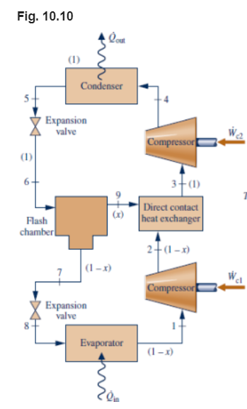
A vapor-compression refrigeration system uses the arrangement shown in Fig. 10.10 (a flash chamber and two-stage compression with intercooling between the stages). Inside the flash chamber, the liquid and vapor components separate into two streams. Refrigerant 134a is the working fluid. Saturated vapor at –28°C enters the first compressor stage. The flash chamber and direct contact heat exchanger operate at 6 bar, and the condenser pressure is 12 bar. Saturated liquid streams at 12 bar and 6 bar enter the high- and low-pressure expansion valves, respectively. If each compressor operates isentropically and the refrigerating capacity of the system is 10 tons... draw the T/S Diagram, and determine (a) the mass flow rate through the evaporator, in kg/s (b) the total power input to both compressors, in kW. (c) the coefficient of performance (COP).


A vapor-compression refrigeration system uses the arrangement shown in Fig. 10.10 (a flash chamber and two-stage compression with intercooling between the stages). Inside the flash chamber, the liquid and vapor components separate into two streams. Refrigerant 134a is the working fluid. Saturated vapor at –28°C enters the first compressor stage. The flash chamber and direct contact heat exchanger operate at 6 bar, and the condenser pressure is 12 bar. Saturated liquid streams at 12 bar and 6 bar enter the high- and low-pressure expansion valves, respectively. If each compressor operates isentropically and the refrigerating capacity of the system is 10 tons...
draw the T/S Diagram, and determine
(a) the mass flow rate through the evaporator, in kg/s
(b) the total power input to both compressors, in kW.
(c) the coefficient of performance (COP).


Trending now
This is a popular solution!

Step by step
Solved in 5 steps with 5 images


