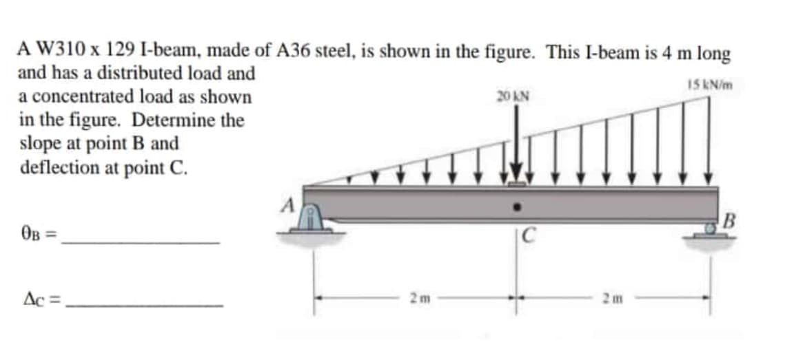
A W310 x 129 I-beam, made of A36 steel, is shown in the figure. This I-beam is 4 m long and has a distributed load and a concentrated load as shown 15 kN/m 20 AN in the figure. Determine the slope at point B and deflection at point C. OB = C Ac = 2 m 2m
Q: A cantilever beam ACB supports two concentrated loads P, and P2, as shown in the following figure.…
A: Draw a diagram for the problem. Here, x is the distance of the cross-section at which the bending…
Q: _Is4lhVkfYEXQZh-UZqdpqqMbGT. 1/ 2 100% 1) For beam shown below, find reaction forces in supports A &…
A:
Q: BP4: A simply supported beam of constant El and length L is supporting a distributed load omega w…
A: The given beam is as shown below, To determine deflection at C by Castilagino's method we will…
Q: . A cantilever beam with square cross-section of 6 mm side is subjected to a load of 2 kN normal to…
A: Load, W= 2 kN= 2000 NSide length of the square, a= 6 mmYoung's modulus, E= 210 GPa= 210000…
Q: Question 1) F=36 kN single load, M=48 kN.m moment and w=20 kN/m distributed load act on the beam…
A:
Q: . Figure shows a simply supported beam of span 5m carrying two point loads. Find a). The deflection…
A:
Q: Question 1) F=16 kN single load, M=22 kN.m moment and w=11 kN/m distributed load are acting on the…
A: As per the guidelines we will answer the first three subparts for you. for the rest of the subparts…
Q: The maximum deflection & in a simply supported beam of length L carrying a concentrated load P at…
A: Since the load is acting at the midpoint which is symmetric from both ends, We can directly write…
Q: 2. The simply supported beam shown in the figure consists of a W410x60 structural steel wide-flange…
A: A moment is a movement of the body when a body is rotating on an axis. The moment is also known as…
Q: Question 1) F=35 kN single load, M=45 kN.m moment and w=16 kN/m distributed load are acting on the…
A: A pin support will exert both horizontal and vertical components of reaction. The support A is pin…
Q: The slope at end of the point A (ii) The deflection at point C
A:
Q: Q5: A steel beam of length 7m is built in at both ends. It has a depth of 500mm and the second…
A:
Q: 1. A semi-infinite steel beam of second moment of area I, = 4.0 × 10° mmª is supported on an elastic…
A: Write the given information.
Q: Consider a portion on the aircraft floor beam of a commercial plane with a maximum deflection of…
A: Shear force is a load acting toward a path that is corresponding to (over the highest point of) a…
Q: A cantilever beam carries a varying load as shown in the figure. If E=200,000 Mpa and =120x106 mm4…
A:
Q: The simply supported W8X24 A-36 steel beam AB is loaded as shown in the figure. What is the slope of…
A:
Q: F=16 kN single load, M=22 kN.m moment and w=11 kN/m distributed load are acting on the beam whose…
A: Given data, The inclined applied force, F = 16000 N The applied moment, M = 22000 Nm The applied…
Q: A: 56m 47Nm Determine the maximum deflection and maximum slope of the simply supported beam of…
A:
Q: 3P2: A simply supported beam of constant El and length L IS supporting a distributed load omega w…
A:
Q: Since the beam AB shown in the figure is P = 60 kN, L = 3 m and E = 200 GPa, find the deflection at…
A:
Q: Q2. A simple supported beam of span 12m carries two points loads 220 KN & 135 KN at 3m & 8m from…
A: Given data, Length of the beam, L = 12 m Two point loads, P1 = 220 KN = 220×103 N at 3 m from left…
Q: Problem: Using The moment Area method, determine the slope at point C and D of the overhanging beam…
A: Section =100×200E=75GpaI=bd312=100×200312I=66,666,666.66mm
Q: A cantilever beam of length L1= 250 mm, L2= 250 mm, and L3= 300 mm supports two loads of P1 = 4 kN…
A:
Q: P B A 21 21 1.50 m 1.50 m 1.50 m 1.50 m
A: given data; ⇒lets take reaction force at A=RA⇒lets take reaction force at…
Q: Hw: Find te slope and deflection in the section (A-A) and the Section cB-B) for the beam Shown.…
A: Given Data: The uniform load is w= 2 kN/m. The span of the beam is L=4.5 m The value of E=205 GPa.…
Q: Determine the deflection at the end of the overhang by applying the second moment area theorem. The…
A: Given Data Modulus of elasticity, E=500000 MPa=5*1011 N/m2. Due to symmetric load, RA=RB=10 KN…
Q: Calculate the shape factor j for the wide-flange beam shown in the figure if h = 12.2 in., b =…
A: Given Data The height of the beam is: h=12.2 in The width of the beam is: b=8.08 in The flange…
Q: F=22 kN single load, M=26 kN.m moment and w=17 kN/m distributed load are acting on the beam whose…
A: Given data, The inclined applied force, F = 22000 N The applied moment, M = 26000 Nm The applied…
Q: Installed appointment of a beam made of a U profile in the figure Find the length c of the overhangs…
A: FBD of given fig. Finding reactionRA+RB=30+30 +40×6RA+RB=300KnSo RA=RB=3002=150Kn
Q: 9.5-2 A simply supported beam (E = 12 GPa) car- Tics a uniformly distributed load q = 125 N/m, and a…
A: Find the maximum deflection of the beam.
Q: ..s) The beam shown is fixed at A and to be supported by rod BC at B. The beam carries a uniform…
A: we have to calculate the deflection without rod
Q: -30. Calculate the deflection at point C of a beam subjected to uniformly distributedload w = 275…
A:
Q: Q 1. A simple supported beam of span 9m carries two points loads 210 KN & 125 KN at 2m & 6m from…
A: Given:- the span of simple supported beam=9m Uniform distribution load throughout the beam…
Q: For The beam shown in The Figure belw. find deflection at point B FI =12000 KN wm? P= 50 KN M225KN.m…
A:
Q: Question 1) F=35 kN single load, M=45 kN.m moment and w=16 kN/m distributed load are acting on the…
A:
Q: Q/ For the beam shown in the figure below, find deflection and rotation at point B. EI=12000 kN.m?.…
A:
Q: 12 kN 8 kN/m 50 kN-m A B -5 m 4 m-
A: Given Total length of beam L=5+4=9 m Uniform load of magnitude 8 kN/m acting over a span of 5 m from…
Q: ..s) The beam shown is fixed at A and to be supported by rod BC at B. The beam carries a uniform…
A:
Q: 9.5-2 A simply supported beam (E = 12 GPa) car- THes a uniformly distributed load q point load P =…
A:
Q: Obtain the equation of the deflection curve for the simple supported beam AB (see figure). Also,…
A:
Q: Since the safety normal stress of the wood used for the beam and loading condition shown in the…
A: Safety normal stress, σmax=12 MPa=12*103 kPa
Q: h F The beam of length 5.9 (m) and cross section base 0.10 (m) and height 0.16 (m) shown is made of…
A:
Q: 7.17 The figure shows a steel beam which is fixedly clamped in A, and which rests on a roller…
A:
Q: Find the deflection at the mid-point BC of the loaded beam as shown in the figure by the double…
A:
Q: . A beam sinmply supported at the concentrated load P as shown in Fig. P-1334. If the maxımun…
A: given data;maximum flexural stress (τ)=20ksi=20*103lb/in2
Q: b. Determine the deflection of the beam at midpoint for the beam loading system shown in the figure…
A:
Q: Question 1) F=22 kN single load, M=26 kN.m moment and w=17 kN/m distributed load are acting on the…
A: Note: As per our guidelines we are supposed to answer only the first 3 sub-parts. Kindly repost…
Q: bläi 4 For a beam, as shown in the below figure, the deflection at the free end are 8 kN 6kN/m A_c!…
A: A free-body diagram of the above beam is given as, On using force equilibrium in a vertical…
Trending now
This is a popular solution!
Step by step
Solved in 4 steps with 4 images
- A wide-flange member (W200 × 22.5) is compressed by axial loads that have a resultant P acting at the point shown in the figure. The member has modulus of elasticity E = 200 GPa and pinned conditions at the ends. Lateral supports prevent any bending about the weak axis of the cross section. If the length of the member is 6.2 m and the deflection is limited to 6.5 mm. what is the maximum allowable load Pallow.Determine the plastic modulus Z and shape factor/for a W 12 x 14 wide-flange beam. Obtain the cross-sectional dimensions and section modulus of the beam from Table F-l(a) in Appendix F.A simple beam with a W 10 x 30 wide-flange cross section supports a uniform load of intensity q = 3.0 kips/ft on a span of length L = 12 ft (sec figure). The dimensions of the cross section are q = 10.5 in., b = 5.81 in., t1= 0.510 in., and fw = 0.300 in. Calculate the maximum shear stress tjuly on cross section A—A located at distance d = 2.5 ft from the end of the beam. Calculate the shear stress rat point Bon the cross section. Point B is located at a distance a = 1.5 in. from the edge of the lower flange.
- A simple beam AB of length L and height h (see figure) is heated in such a manner that the temperature difference 7= T{between the bottom and top of the beam is proportional to the distance from support A: that is, assume the temperature difference varies linearly along the beam: T2- Tt= Tax in which 7"0 is a constant having units of temperature (degrees) per unit distance. Determine the maximum deflection SW9Xof the beam, Repeat for a quadratic temperature variation along the beam, so T2+T1= TaxThe tapered cantilever beam AB shown in the figure has a thin-walled, hollow circular cross sections of constant thickness t. The diameters at the ends A and B are dAand dB= 2dA, respectively. Thus, the diameter d and moment of inertia / at distance x from the free end are, respectively, in which IAis the moment of inertia at end A of the beam. Determine the equation of the deflection curve and the deflection 8 Aat the free end of the beam due to the load P.The cross section of a sand wie h beam consisting of aluminum alloy faces and a foam core is shown in the figure. The width b of the beam is 8.0 in, the thickness I of the faces is 0.25 in., and the height hcof the core is 5.5 in. (total height h = 6.0 in). The moduli of elasticity are 10.5 × 10⁶ psi for the aluminum faces and 12.000 psi for the foam core. A bending moment M = 40 kip-in. acts about the z axis. Determine the maximum stresses in the faces and the core using (a) the general theory for composite beams and (b) the approximate theory for sandwich beams.
- A cantilever beam AB having rectangular cross sections with varying width bxand varying height hxis subjected to a uniform load of intensity q (sec figure). If the width varies linearly with x according to the equation hx= bBxiL^ how should the height hxvary as a function of v in order to have a fully stressed beam? (Express hxin terms of the height hBat the fixed end of the beam.)The hollow box beam shown in the figure is subjected to a bending moment M of such magnitude that the flanges yield but the webs remain linearly elastic. (a) Calculate the magnitude of the moment M if the dimensions of the cross section are A = 15 in., A] = 12.75 in., h = 9 in., and ey =7.5 in. Also, the yield stress is eY = 33 ksi. (b) What percent of the moment M is produced by the elastic core?A simple beam ACB supports a uniform load of intensity q on the left-hand half of the span (see figure). Determine the angle of rotation ÔBat support B>(Obtain the solution by using the modified form of Castigliano's theorem.)
- The cantilever beam shown in the figure supports a triangularly distributed load of maximum intensity qü. Determine the deflection SBat the free end B. (Obtain the solution by determining the strain energy of the beam and then using Castigliano's theorem.)A simple beam AB of length L is loaded at the left-hand end by a couple of moment MQ(see figure). Determine the angle of rotation 0 , at support A. (Obtain the solution by determining the strain energy of the beam and then using Castigliano's theorem.)A hollow box beam with height h = 16 in,, width h = 8 in,, and constant wall thickness r = 0.75 LiL is shown in the figure. The beam is constructed of steel with yield stress ty = 32 ksi. Determine the yield moment My, plastic moment A/p, and shape factor.