(a) Why does synchronisation failure occur?

Chapter22: Sequence Control
Section: Chapter Questions
Problem 6SQ: Draw a symbol for a solid-state logic element AND.

Related questions

Question
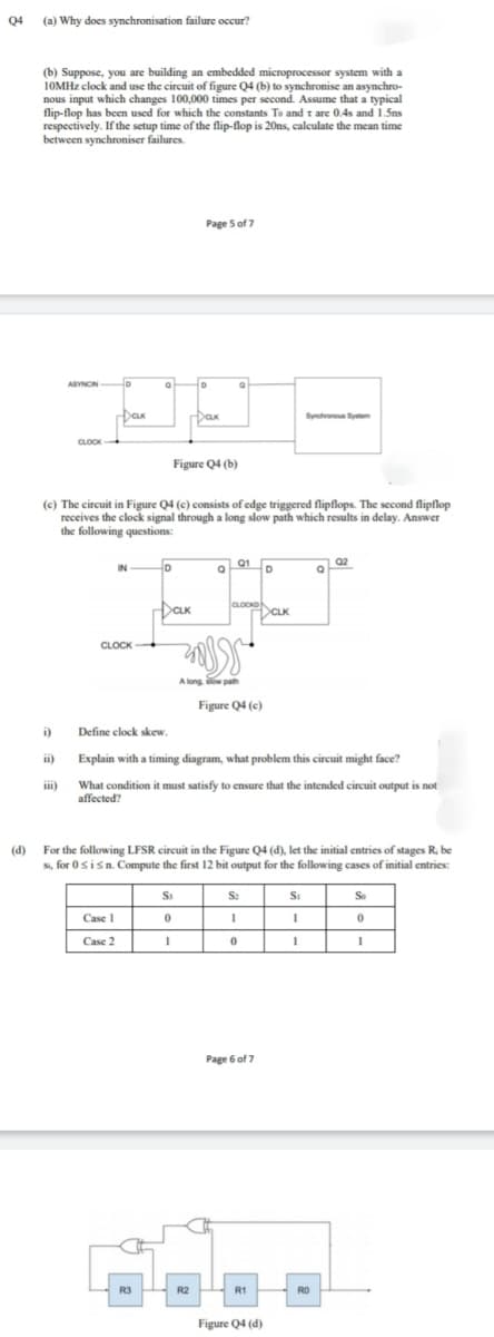
Transcribed Image Text:Q4 (a) Why does synchronisation failure occur?
(b) Suppose, you are building an embedded microprocessor system with a
10MHZ clock and use the circuit of figure Q4 (b) to synchronise an asynchro-
nous input which changes 100,000 times per second. Assume that a typical
flip-flop has been used for which the constants To and t are 0.4s and 1.5ns
respectively. If the setup time of the flip-flop is 20ns, calculate the mean time
between synchroniser failures.
Page S of 7
ASYNCIN
Syncvonous System
CLOCK
K
Figure Q4 (b)
(c) The circuit in Figure Q4 (c) consists of edge triggered flipflops. The second flipflop
receives the clock signal through a long slow path which results in delay. Answer
the following questions:
Q2
IN D
아
01
D
CLOCKD
Dax
CLK
CLOCK
A long slow path
Figure Q4 (c)
i)
Define elock skew.
ii)
Explain with a timing diagram, what problem this circuit might face?
What condition it must satisfy to ensure that the intended circuit output is not
affected?
ii)
(d) For the following LFSR circuit in the Figure Q4 (d), let the initial entries of stages R. be
Si, for 0sisn. Compute the first 12 bit output for the following cases of initial entries:
S:
Si
So
Case 1
Case 2
Page 6 of 7
R3
R2
R1
RO
Figure Q4 (d)
Expert Solution
This question has been solved!
Explore an expertly crafted, step-by-step solution for a thorough understanding of key concepts.

Step by step
Solved in 2 steps

Knowledge Booster


Learn more about
Need a deep-dive on the concept behind this application? Look no further. Learn more about this topic, electrical-engineering and related others by exploring similar questions and additional content below.Recommended textbooks for you