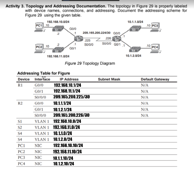
Activity 3. Topology and Addressing Documentation. The topology in Figure 29 is properly labeled with device names, connections, and addressing. Document the addressing scheme for Figure 29 using the given table. 192.168.10.0/24 10.1.1.0/24 PC1.10 .10 PC3 GO/O 209.165.200.224/30 GOO 226 so00 GO/11 225 PC2 .10 10 pca G0/1 192.168.11.0/24 10.1.2.0/24 Figure 29 Topology Diagram Addressing Table for Figure Device Interface GO/0 G0/1 IP Address 192.168.10.1/24 Subnet Mask Default Gateway R1 N/A 192.168.1.1/24 N/A So/0/0 209.165.200.225/30 N/A R2 GO/0 10.1.1.1/24 N/A GO/1 10.1.2.1/24 N/A SO/0/0 209.165.200.226/30 N/A VLAN 1 192.168.10.0/24 VLAN 1 192.168.11.0/24 VLAN 1 10,1.1.0/24 VLAN 1 10.1.2.0/24 s1 S2 S4 S4 PC1 NIC 192.168.10.10/24 PC2 NIC 192.168.11.10/24 PC3 NIC 10.1.1.10/24 PC4 NIC 10.12.10/24
Activity 3. Topology and Addressing Documentation. The topology in Figure 29 is properly labeled with device names, connections, and addressing. Document the addressing scheme for Figure 29 using the given table. 192.168.10.0/24 10.1.1.0/24 PC1.10 .10 PC3 GO/O 209.165.200.224/30 GOO 226 so00 GO/11 225 PC2 .10 10 pca G0/1 192.168.11.0/24 10.1.2.0/24 Figure 29 Topology Diagram Addressing Table for Figure Device Interface GO/0 G0/1 IP Address 192.168.10.1/24 Subnet Mask Default Gateway R1 N/A 192.168.1.1/24 N/A So/0/0 209.165.200.225/30 N/A R2 GO/0 10.1.1.1/24 N/A GO/1 10.1.2.1/24 N/A SO/0/0 209.165.200.226/30 N/A VLAN 1 192.168.10.0/24 VLAN 1 192.168.11.0/24 VLAN 1 10,1.1.0/24 VLAN 1 10.1.2.0/24 s1 S2 S4 S4 PC1 NIC 192.168.10.10/24 PC2 NIC 192.168.11.10/24 PC3 NIC 10.1.1.10/24 PC4 NIC 10.12.10/24

Principles of Information Security (MindTap Course List)
6th Edition
ISBN:9781337102063
Author:Michael E. Whitman, Herbert J. Mattord
Publisher:Michael E. Whitman, Herbert J. Mattord
Chapter6: Security Technology: Access Controls, Firewalls, And Vpns
Section: Chapter Questions
Problem 13RQ

Related questions
Question
100%
answer Subnet Mask and Default Gateway
Transcribed Image Text:Activity 3. Topology and Addressing Documentation. The topology in Figure 29 is properly labeled
with device names, connections, and addressing. Document the addressing scheme for
Figure 29 using the given table.
192.168.10.0/24
PC1 .10
10.1.1.0/24
.10 PC3
53
209.165.200.224/30 GO/O
226
225
sooio
so/o/o GO'1
PC2 .10
10 PC4
GO/1
192.168.11.0/24
10.1.2.0/24
Figure 29 Topology Diagram
Addressing Table for Figure
Device Interface
R1
IP Address
Subnet Mask
Default Gateway
GO/0
192.168.10.1/24
N/A
GO/1
192.168.11.1/24
N/A
So/0/0
209.165.200.225/ao
N/A
R2
GO/0
10.1.1.1/24
N/A
GO/1
10.1.2.1/24
N/A
SO/0/0
209.165.200.226/30
N/A
VLAN 1 192.168.10.0/24
VLAN 1 192.168.11.0/24
VLAN 1 10.1.1.0/24
S2
S4
S4
VLAN 1 10.1.2.0/24
PC1
NIC
192.168.10.10/24
PC2
NIC
192.168.11.10/24
PC3
NIC
10.1.1.10/24
PC4
NIC
10.1.2.10/24
Expert Solution
This question has been solved!
Explore an expertly crafted, step-by-step solution for a thorough understanding of key concepts.

Step by step
Solved in 3 steps

Knowledge Booster


Learn more about
Need a deep-dive on the concept behind this application? Look no further. Learn more about this topic, computer-science and related others by exploring similar questions and additional content below.Recommended textbooks for you
Principles of Information Security (MindTap Cours…
Computer Science
ISBN:
9781337102063
Author:
Michael E. Whitman, Herbert J. Mattord
Publisher:
Cengage Learning
Principles of Information Security (MindTap Cours…
Computer Science
ISBN:
9781337102063
Author:
Michael E. Whitman, Herbert J. Mattord
Publisher:
Cengage Learning