Aim of the Experiment Creating a calibration curve for an orifice. The measuring nozzle is used as a reference. Preparing the Experiment 7 ● Equip orifice holder with desired orifice disk ● ● ● Flow Rate Measurement with Orifice gunt 230 ● ● Disassemble the orifice holder by loosening the four screws in the center. Place the orifice disk with the desired diameter in the center of the recess. Reassemble the holder. Ensure that the orifice disk is centered, and the sealing rings are seated properly in the grooves. Use the union nuts to attach the orifice holder to the measuring nozzle and intake connection. Note: the longer end is the abatement section of the inlet and must be connected to the measuring nozzle. Procedure Connect the pressure measurement points to the differential pressure manometer as shown. 032mm, 025mm: Measuring range 0...600mbar - 019mm, 012mm: Measuring range 0....1mbar. Connect the pressure measurement point for the measuring nozzle to the negative connection of the velocity display. Switch on fan and set the desired flow rate via the speed. ● Record the velocity c at the measuring nozzle and the differential pressure AP. Adjust the flow rate accordingly via the speed and repeat the measurement. Repeat the series of measurement for other orifice diameters. PRACTICAL EXPERIMENT
Aim of the Experiment Creating a calibration curve for an orifice. The measuring nozzle is used as a reference. Preparing the Experiment 7 ● Equip orifice holder with desired orifice disk ● ● ● Flow Rate Measurement with Orifice gunt 230 ● ● Disassemble the orifice holder by loosening the four screws in the center. Place the orifice disk with the desired diameter in the center of the recess. Reassemble the holder. Ensure that the orifice disk is centered, and the sealing rings are seated properly in the grooves. Use the union nuts to attach the orifice holder to the measuring nozzle and intake connection. Note: the longer end is the abatement section of the inlet and must be connected to the measuring nozzle. Procedure Connect the pressure measurement points to the differential pressure manometer as shown. 032mm, 025mm: Measuring range 0...600mbar - 019mm, 012mm: Measuring range 0....1mbar. Connect the pressure measurement point for the measuring nozzle to the negative connection of the velocity display. Switch on fan and set the desired flow rate via the speed. ● Record the velocity c at the measuring nozzle and the differential pressure AP. Adjust the flow rate accordingly via the speed and repeat the measurement. Repeat the series of measurement for other orifice diameters. PRACTICAL EXPERIMENT

Elements Of Electromagnetics
7th Edition
ISBN:9780190698614
Author:Sadiku, Matthew N. O.
Publisher:Sadiku, Matthew N. O.
ChapterMA: Math Assessment
Section: Chapter Questions
Problem 1.1MA

Related questions

Question
Good morning,
Kindly assist me with this experimental calculations as well as graphical representation of the experiment
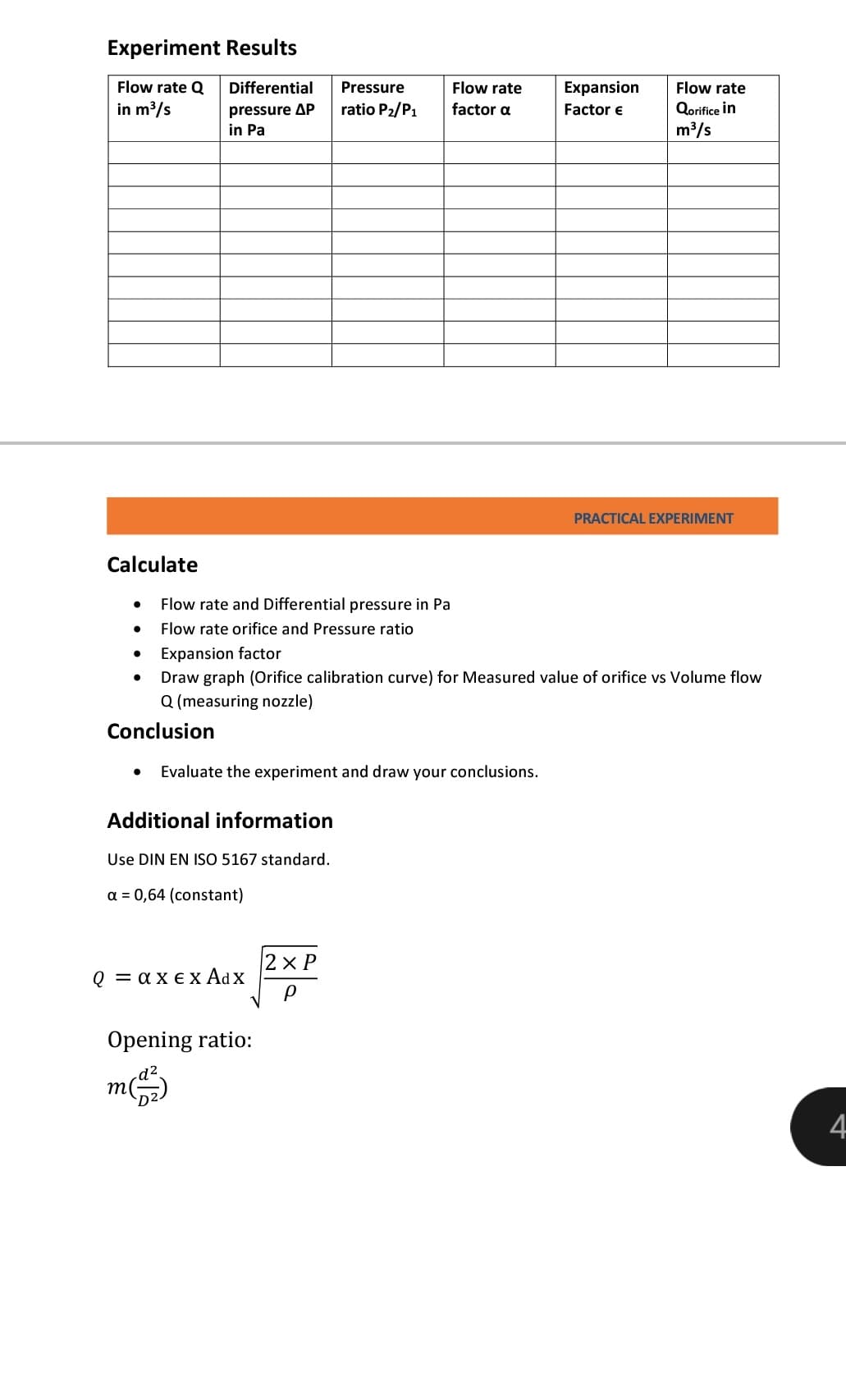
Transcribed Image Text:Experiment Results
Flow rate Q Differential
in m³/s
Calculate
●
●
pressure AP
in Pa
●
Flow rate and Differential pressure in Pa
Flow rate orifice and Pressure ratio
Expansion factor
Additional information
Use DIN EN ISO 5167 standard.
a = 0,64 (constant)
Pressure
ratio P₂/P1
Evaluate the experiment and draw your conclusions.
Q = axex Adx
Draw graph (Orifice calibration curve) for Measured value of orifice vs Volume flow
Q (measuring nozzle)
Conclusion
Opening ratio:
m(1)
Flow rate
factor a
2xP
P
Expansion
Factor €
Flow rate
Qorifice in
m³/s
PRACTICAL EXPERIMENT
4
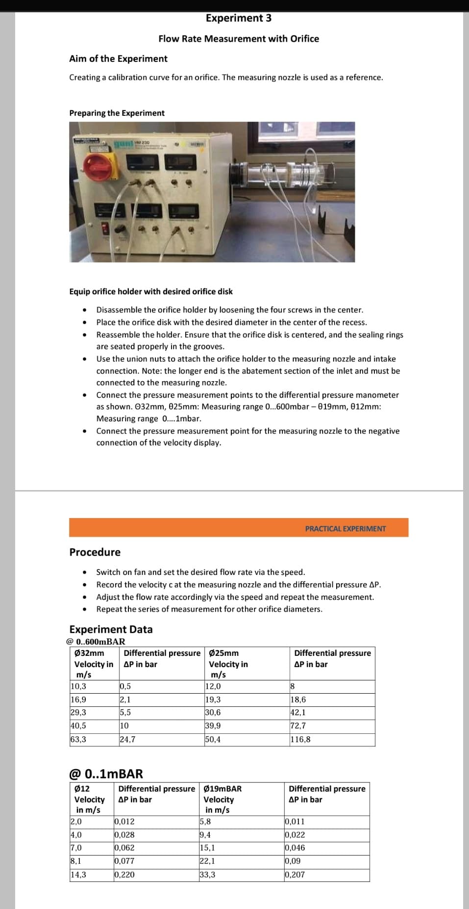
Transcribed Image Text:Aim of the Experiment
Creating a calibration curve for an orifice. The measuring nozzle is used as a reference.
Preparing the Experiment
●
Equip orifice holder with desired orifice disk
●
●
●
●
●
●
SEASE 230
Procedure
10,3
16,9
29,3
40,5
63,3
Disassemble the orifice holder by loosening the four screws in the center.
Place the orifice disk with the desired diameter in the center of the recess.
Reassemble the holder. Ensure that the orifice disk is centered, and the sealing rings
are seated properly in the grooves.
Use the union nuts to attach the orifice holder to the measuring nozzle and intake
connection. Note: the longer end is the abatement section of the inlet and must be
connected to the measuring nozzle.
2,0
4,0
7,0
8,1
14,3
Experiment 3
Flow Rate Measurement with Orifice
Connect the pressure measurement points to the differential pressure manometer
as shown. 032mm, 025mm: Measuring range 0...600mbar - 019mm, 012mm:
Measuring range 0....1mbar.
Connect the pressure measurement point for the measuring nozzle to the negative
connection of the velocity display.
Experiment Data
@ 0..600mBAR
Ø32mm
Velocity in
m/s
Switch on fan and set the desired flow rate via the speed.
Record the velocity c at the measuring nozzle and the differential pressure AP.
Adjust the flow rate accordingly via the speed and repeat the measurement.
Repeat the series of measurement for other orifice diameters.
Differential pressure Ø25mm
AP in bar
Velocity in
m/s
0,5
2,1
5,5
10
24,7
@ 0..1mBAR
Ø12
Velocity
in m/s
0,012
0,028
0,062
0,077
0,220
12,0
19,3
30,6
39,9
50,4
Differential pressure Ø19mBAR
ΔΡ in bar
Velocity
in m/s
5,8
9,4
15,1
22,1
33,3
PRACTICAL EXPERIMENT
Differential pressure
ΔΡ in bar
18
18,6
42,1
72,7
116,8
Differential pressure
ΔΡ in bar
0,011
0,022
0,046
0,09
0,207
Expert Solution
This question has been solved!
Explore an expertly crafted, step-by-step solution for a thorough understanding of key concepts.

Step by step
Solved in 3 steps with 3 images

Knowledge Booster


Learn more about
Need a deep-dive on the concept behind this application? Look no further. Learn more about this topic, mechanical-engineering and related others by exploring similar questions and additional content below.Recommended textbooks for you
Elements Of Electromagnetics
Mechanical Engineering
ISBN:
9780190698614
Author:
Sadiku, Matthew N. O.
Publisher:
Oxford University Press

Mechanics of Materials (10th Edition)
Mechanical Engineering
ISBN:
9780134319650
Author:
Russell C. Hibbeler
Publisher:
PEARSON

Thermodynamics: An Engineering Approach
Mechanical Engineering
ISBN:
9781259822674
Author:
Yunus A. Cengel Dr., Michael A. Boles
Publisher:
McGraw-Hill Education
Elements Of Electromagnetics
Mechanical Engineering
ISBN:
9780190698614
Author:
Sadiku, Matthew N. O.
Publisher:
Oxford University Press
Mechanics of Materials (10th Edition)
Mechanical Engineering
ISBN:
9780134319650
Author:
Russell C. Hibbeler
Publisher:
PEARSON
Thermodynamics: An Engineering Approach
Mechanical Engineering
ISBN:
9781259822674
Author:
Yunus A. Cengel Dr., Michael A. Boles
Publisher:
McGraw-Hill Education

Control Systems Engineering
Mechanical Engineering
ISBN:
9781118170519
Author:
Norman S. Nise
Publisher:
WILEY

Mechanics of Materials (MindTap Course List)
Mechanical Engineering
ISBN:
9781337093347
Author:
Barry J. Goodno, James M. Gere
Publisher:
Cengage Learning

Engineering Mechanics: Statics
Mechanical Engineering
ISBN:
9781118807330
Author:
James L. Meriam, L. G. Kraige, J. N. Bolton
Publisher:
WILEY