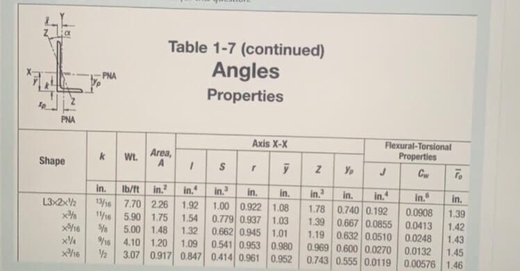
A L 3 x 2 x ¼ is connected to a gusset plate via six bolts. The nominal diameter of the bolt is 0.25 inches, the pitch spacing is 1.75 inches, the gage spacing is 2 inches, and the thickness of the connection is (¼) inch. The yield stress is 50 Ksi and the ultimate stress is 60 Ksi. Consider section line (a-a') for the analysis. . a. What is the effective net area (Ae) of the angle section in inches2 [a-a']? (The shear lag factor is "0.80") b. What is the design tensile yielding strength in Kips for the steel member? c. What is the design tensile rupture strength in Kips for the steel member? d. What is the minimum Factor of Safety if a tensile load of 23 Kips is applied to the angle section?

Steel Design (Activate Learning with these NEW titles from Engineering!)
6th Edition
ISBN:9781337094740
Author:Segui, William T.
Publisher:Segui, William T.
Chapter3: Tension Members
Section: Chapter Questions
Problem 3.3.8P
icon
Related questions
Question
100%

L 3 x 2 x ¼ is connected to a gusset plate via six bolts. The nominal diameter of the bolt is 0.25 inches, the pitch spacing is 1.75 inches, the gage spacing is 2 inches, and the thickness of the connection is (¼) inch. The yield stress is 50 Ksi and the ultimate stress is 60 Ksi. Consider section line (a-a') for the analysis.

.

a. What is the effective net area (Ae) of the angle section in inches2 [a-a']?
(The shear lag factor is "0.80")

b. What is the design tensile yielding strength in Kips for the steel member?

c. What is the design tensile rupture strength in Kips for the steel member?

d. What is the minimum Factor of Safety if a tensile load of 23 Kips is applied to the angle section?


please make sure the answer is correct 100%

I only need the final answers

Table 1-7 (continued)
Angles
PNA
Properties
PNA
Axis X-X
Flexural-Torsional
Area,
Properties
k
Wt.
Shape
Cw
To
in.
in.?
in.
in.
1.00 0.922 1.08
0.779 0.937 1.03
0.662 0.945 1.01
0.541 0.953 0.980
Ib/ft
in.
in.
in.
in.
in.
in.
in.
L3x2x½
x%%
13/16 7.70 2.26
1.78 0.740 0.192
1.92
0.0908
1.39
11/16 5.90 1.75
5.00 1.48
/16 4.10 1.20
1.54
1.39 0.667 0.0855 0.0413
1.42
5/8
1.32
1.19 0.632 0.0510
0.0248
0.969 0.600 0.0270 0.0132
0.743 0.555 0.0119 0.00576 1.46
1.43
1.45
1.09
1/2
3.07 0.917 0.847 0.414 0.961 0.952
S4
Transcribed Image Text:Table 1-7 (continued) Angles PNA Properties PNA Axis X-X Flexural-Torsional Area, Properties k Wt. Shape Cw To in. in.? in. in. 1.00 0.922 1.08 0.779 0.937 1.03 0.662 0.945 1.01 0.541 0.953 0.980 Ib/ft in. in. in. in. in. in. in. L3x2x½ x%% 13/16 7.70 2.26 1.78 0.740 0.192 1.92 0.0908 1.39 11/16 5.90 1.75 5.00 1.48 /16 4.10 1.20 1.54 1.39 0.667 0.0855 0.0413 1.42 5/8 1.32 1.19 0.632 0.0510 0.0248 0.969 0.600 0.0270 0.0132 0.743 0.555 0.0119 0.00576 1.46 1.43 1.45 1.09 1/2 3.07 0.917 0.847 0.414 0.961 0.952 S4
Expert Solution
steps

Step by step

Solved in 2 steps

Blurred answer
Knowledge Booster
Advanced framing techniques
Learn more about
Need a deep-dive on the concept behind this application? Look no further. Learn more about this topic, civil-engineering and related others by exploring similar questions and additional content below.
Similar questions
  • SEE MORE QUESTIONS
Recommended textbooks for you
Steel Design (Activate Learning with these NEW ti…
Civil Engineering
ISBN:
9781337094740
Author:
Segui, William T.
Publisher:
Cengage Learning