An I-beam is supported with a roller at A and a pin at B. The cross-section of the I-beam is shown. F1 a
An I-beam is supported with a roller at A and a pin at B. The cross-section of the I-beam is shown. F1 a

Mechanics of Materials (MindTap Course List)
9th Edition
ISBN:9781337093347
Author:Barry J. Goodno, James M. Gere
Publisher:Barry J. Goodno, James M. Gere
Chapter5: Stresses In Beams (basic Topics)
Section: Chapter Questions
Problem 5.7.2P: .2 A ligmio.irc ii supported by two vorlical beams consistins: of thin-walled, tapered circular...

Related questions

Question
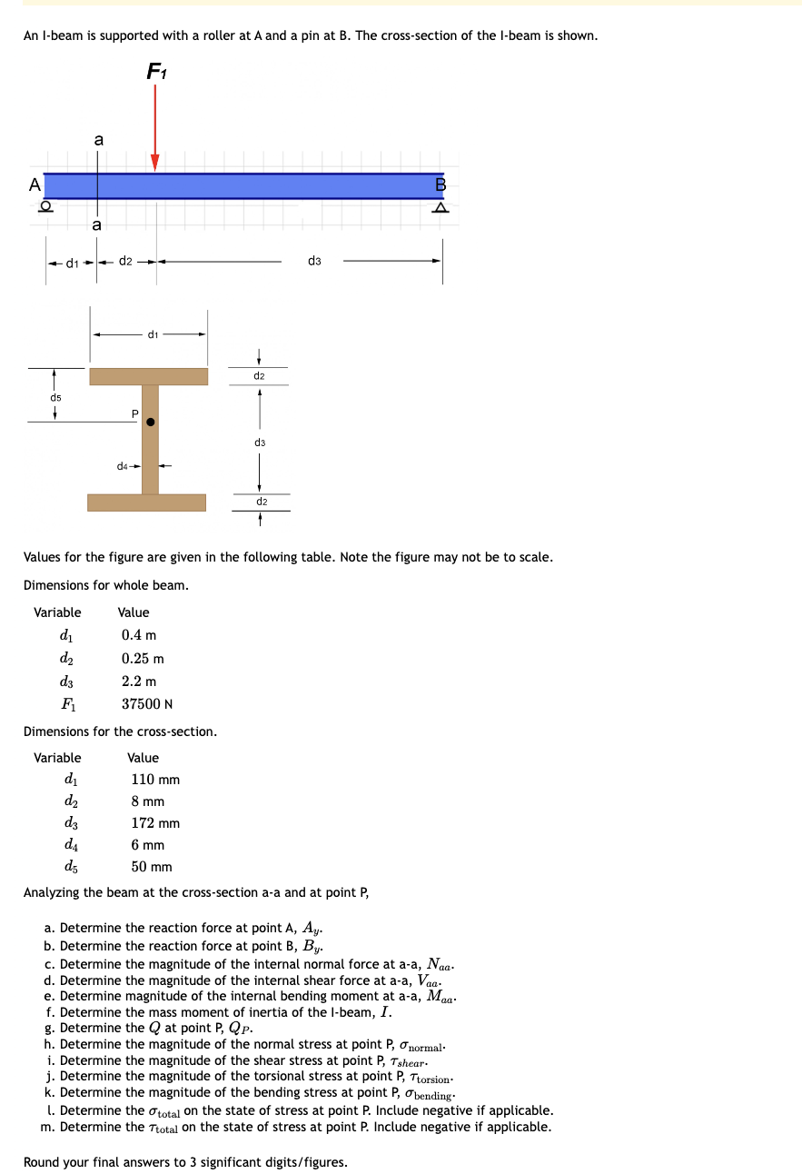
an I-beam is supported with a roller at A and a pin at B. The cross-section of the I-beam is shown.
Transcribed Image Text:An I-beam is supported with a roller at A and a pin at B. The cross-section of the I-beam is shown.
F1
A
ō
a
d1
a
d2
d1
H
d5
P
d4-
d2
d3
d2
d3
B
Values for the figure are given in the following table. Note the figure may not be to scale.
Dimensions for whole beam.
Variable
Value
d₁
0.4 m
d2
0.25 m
d3
2.2 m
F₁
37500 N
Dimensions for the cross-section.
Variable
d₁
d₂
d3
d4
d5
Value
110 mm
8 mm
172 mm
6 mm
50 mm
Analyzing the beam at the cross-section a-a and at point P,
a. Determine the reaction force at point A, Ay.
b. Determine the reaction force at point B, By.
c. Determine the magnitude of the internal normal force at a-a, Naa-
d. Determine the magnitude of the internal shear force at a-a, Vaa-
e. Determine magnitude of the internal bending moment at a-a, Maa.
f. Determine the mass moment of inertia of the I-beam, I.
g. Determine the Qat point P, Qp.
h. Determine the magnitude of the normal stress at point P, σnormal.
i. Determine the magnitude of the shear stress at point P, Tshear-
j. Determine the magnitude of the torsional stress at point P, Ttorsion.
k. Determine the magnitude of the bending stress at point P, bending.
l. Determine the total on the state of stress at point P. Include negative if applicable.
m. Determine the Ttotal on the state of stress at point P. Include negative if applicable.
Round your final answers to 3 significant digits/figures.
Expert Solution
This question has been solved!
Explore an expertly crafted, step-by-step solution for a thorough understanding of key concepts.

Step by step
Solved in 3 steps with 11 images

Knowledge Booster


Learn more about
Need a deep-dive on the concept behind this application? Look no further. Learn more about this topic, mechanical-engineering and related others by exploring similar questions and additional content below.Recommended textbooks for you
Mechanics of Materials (MindTap Course List)
Mechanical Engineering
ISBN:
9781337093347
Author:
Barry J. Goodno, James M. Gere
Publisher:
Cengage Learning
Mechanics of Materials (MindTap Course List)
Mechanical Engineering
ISBN:
9781337093347
Author:
Barry J. Goodno, James M. Gere
Publisher:
Cengage Learning