An "I"-shape beam is subjected to bending. The loading condition and the dimension of its cross-section are shown in Figure A2-1. P=100 KN 10mm 30mm 2m Neutral axis 30mm B 10 mm C Figure A2-1 Determine the reaction forces at connections A and B. Draw the shear force and bending moment diagrams and determine the values of the maximum bending moment that the beam experiences. A (a) (b) 1m 10 mm 50 mm
An "I"-shape beam is subjected to bending. The loading condition and the dimension of its cross-section are shown in Figure A2-1. P=100 KN 10mm 30mm 2m Neutral axis 30mm B 10 mm C Figure A2-1 Determine the reaction forces at connections A and B. Draw the shear force and bending moment diagrams and determine the values of the maximum bending moment that the beam experiences. A (a) (b) 1m 10 mm 50 mm

Mechanics of Materials (MindTap Course List)
9th Edition
ISBN:9781337093347
Author:Barry J. Goodno, James M. Gere
Publisher:Barry J. Goodno, James M. Gere
Chapter5: Stresses In Beams (basic Topics)
Section: Chapter Questions
Problem 5.13.3P: A rectangular beam with semicircular notches, as shown in part b of the figure, has dimensions h =...

Related questions
Question
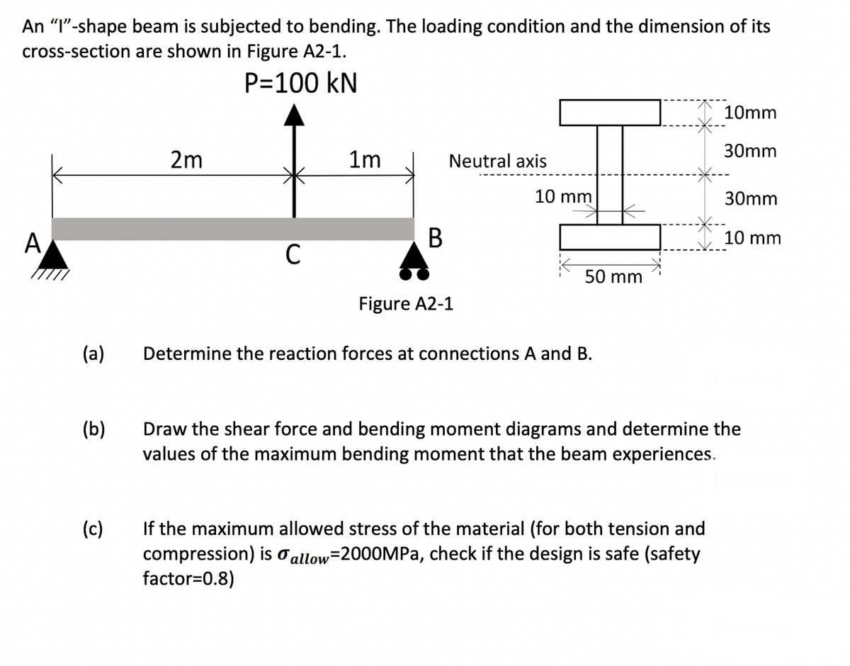
Transcribed Image Text:An "I"-shape beam is subjected to bending. The loading condition and the dimension of its
cross-section are shown in Figure A2-1.
P=100 KN
10mm
30mm
2m
Neutral axis
30mm
A
10 mm
B
с
Figure A2-1
(a)
Determine the reaction forces at connections A and B.
(b)
Draw the shear force and bending moment diagrams and determine the
values of the maximum bending moment that the beam experiences.
(c)
If the maximum allowed stress of the material (for both tension and
compression) is allow=2000MPa, check if the design is safe (safety
factor=0.8)
1m
10 mm
50 mm
Expert Solution
This question has been solved!
Explore an expertly crafted, step-by-step solution for a thorough understanding of key concepts.

Step by step
Solved in 2 steps with 2 images

Knowledge Booster


Learn more about
Need a deep-dive on the concept behind this application? Look no further. Learn more about this topic, mechanical-engineering and related others by exploring similar questions and additional content below.Recommended textbooks for you
Mechanics of Materials (MindTap Course List)
Mechanical Engineering
ISBN:
9781337093347
Author:
Barry J. Goodno, James M. Gere
Publisher:
Cengage Learning
Mechanics of Materials (MindTap Course List)
Mechanical Engineering
ISBN:
9781337093347
Author:
Barry J. Goodno, James M. Gere
Publisher:
Cengage Learning