An impedance coil is connected in parallel with a capacitance C of 12.5 µF. The input voltage to the circuit is 100 V at 31.8 Hz. The phase angle between the two branch currents (Ii and l2) is 120° and the current in the first branch is I, = 0.5A. Determine the following: a) the current l2 and total current b) the value of R and XL c) the value of inductor (L in mH) d) the total impedance e) the power factor f) the value of conductance (G in mu) and sUsceptance (B in µV) g) total admittance
An impedance coil is connected in parallel with a capacitance C of 12.5 µF. The input voltage to the circuit is 100 V at 31.8 Hz. The phase angle between the two branch currents (Ii and l2) is 120° and the current in the first branch is I, = 0.5A. Determine the following: a) the current l2 and total current b) the value of R and XL c) the value of inductor (L in mH) d) the total impedance e) the power factor f) the value of conductance (G in mu) and sUsceptance (B in µV) g) total admittance

Power System Analysis and Design (MindTap Course List)
6th Edition
ISBN:9781305632134
Author:J. Duncan Glover, Thomas Overbye, Mulukutla S. Sarma
Publisher:J. Duncan Glover, Thomas Overbye, Mulukutla S. Sarma
Chapter2: Fundamentals
Section: Chapter Questions
Problem 2.7P: Let a 100V sinusoidal source be connected to a series combination of a 3 resistor, an 8 inductor,...

Related questions
Question
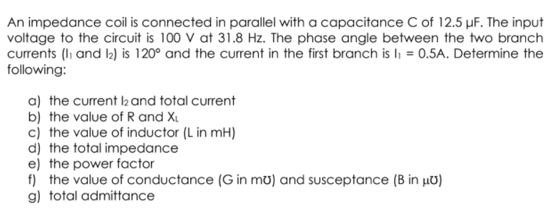
Transcribed Image Text:An impedance coil is connected in parallel with a capacitance C of 12.5 µF. The input
voltage to the circuit is 100 V at 31.8 Hz. The phase angle between the two branch
currents (li and I2) is 120° and the current in the first branch is li = 0.5A. Determine the
following:
a) the current l2 and total current
b) the value of R and XL
c) the value of inductor (L in mH)
d) the total impedance
e) the power factor
f) the value of conductance (G in mu) and susceptance (B in µv)
g) total admittance
Expert Solution
This question has been solved!
Explore an expertly crafted, step-by-step solution for a thorough understanding of key concepts.

Step by step
Solved in 7 steps with 1 images

Knowledge Booster


Learn more about
Need a deep-dive on the concept behind this application? Look no further. Learn more about this topic, electrical-engineering and related others by exploring similar questions and additional content below.Recommended textbooks for you
Power System Analysis and Design (MindTap Course …
Electrical Engineering
ISBN:
9781305632134
Author:
J. Duncan Glover, Thomas Overbye, Mulukutla S. Sarma
Publisher:
Cengage Learning
Power System Analysis and Design (MindTap Course …
Electrical Engineering
ISBN:
9781305632134
Author:
J. Duncan Glover, Thomas Overbye, Mulukutla S. Sarma
Publisher:
Cengage Learning