An S178 x 30 American standard I-beam (see Appendix A) is loaded and supported as shown below. (a) Draw complete shear force and bending moment diagrams for the beam. (b) Determine the maximum flexural stress in the beam. Y -2 m 15 kN/m 25 kN Y Y 2 m 2 m- I
An S178 x 30 American standard I-beam (see Appendix A) is loaded and supported as shown below. (a) Draw complete shear force and bending moment diagrams for the beam. (b) Determine the maximum flexural stress in the beam. Y -2 m 15 kN/m 25 kN Y Y 2 m 2 m- I

Mechanics of Materials (MindTap Course List)
9th Edition
ISBN:9781337093347
Author:Barry J. Goodno, James M. Gere
Publisher:Barry J. Goodno, James M. Gere
Chapter6: Stresses In Beams (advanced Topics)
Section: Chapter Questions
Problem 6.10.4P: A steel beam of rectangular cross section is 40 mm wide and 80 mm high (see figure). The yield...

Related questions
Question
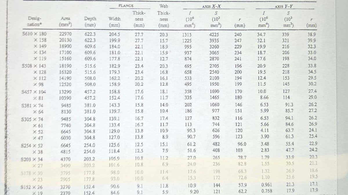
Transcribed Image Text:Desig-
nation*
S610 x 180
X 158
X 149
x 134
X 119
S508 x 143
X 128
X 112
X98
S457 x 104
X 81
S381 % 74
X 64
$305 X 74
X 61
X 52
X 47
8254 % 52
X 38
8203 X 34
% 27
$178 % 30
X 23
9152 X 26
X 19
Area
(mm²)
22970
20130
18900
17100
15160
18190
16320
14190
12520
13290
10390
9485
8130
9485
7740
6645
6030
6645
4815
4370
3490
3795
2905
3270
2370
Depth Width
(mm)
622.3
622.3
609.6
609.6
609.6
515.6
515.6
508.0
508.0
457.2
457.2
381.0
381.0
304.8
304.8
304.8
304.8
254.0
254.0
203.2
203.2
177.8
177.8
FLANGE
152.4
152.4
204.5
199.9
184.0
181.0
177.8
182.9
179.3
162.2
158.9
158.8
152.4
143.3
139.7
139.1
133.4
129.0
127.0
125,6
1184
105.9
101.6
98.0
93.0
90.6
84.6
Thick-
ness
(mm)
27.7
27.7
22.1
22.1
22.1
23.4
23.4
20.2
20.2
17.6
17.6
15.8
15.8
16.7
16.7
13.8
13.8
12.5
12.5
10.8
10.8
10.0
10.0
9.1
9.1
Web
Thick-
ness
(mm)
20.3
15.7
18.9
15.9
12.7
20.3
16.8
16.1
12.8
18.1
11.7
14.0
10.4
17.4
11.7
10.9
8.9
15.1
7,9
11.2
6.9
114
6.4
11.8
5,9
I
(106
mm²)
1315
1225
995
937
874
695
658
533
495
358
335
202
186
127
113
95.3
90.7
61.2
51.6
27.0
24.0
17.6
15.3
10.9
9.20
AXIS X-X
S
(10³
mm³)
4225
3935
3260
3065
2870
2705
2540
2100
1950
1690
1465
1060
977
832
744
626
596
482
408
265
236
198
172
144
121
(mm)
240
247
229
234
241
196
200
194
199
170
180
146
151
116
121
120
123
96.0
103
78.7
82.8
68.3
72.6
57.9
62.2
I
(106
mm)
34.7
32.1
19.9
18.7
17.6
20.9
19.5
12.4
11.5
10.0
8.66
6.53
5.99
6.53
5.66
4.11
3.90
3.48
2.83
1.79
1.55
1.32
1.10
0.961
0.758
AXIS X-Y
S
(103
mm³)
339
321
216
206
198
228
218
153
145
127
114
91.3
85.7
94.1
84.6
63.7
61.3
55.4
47.7
33.9
30.5
26.9
23.6
21.3
17.9
(mm)
38.9
39.9
32.3
33.0
34.0
33.8
34.5
29.5
30.2
27.4
29.0
26.2
27.2
26.2
26.9
24.1
25.4
22.9
24.2
20.3
21.1
18.6
19.5
17.1
17.9
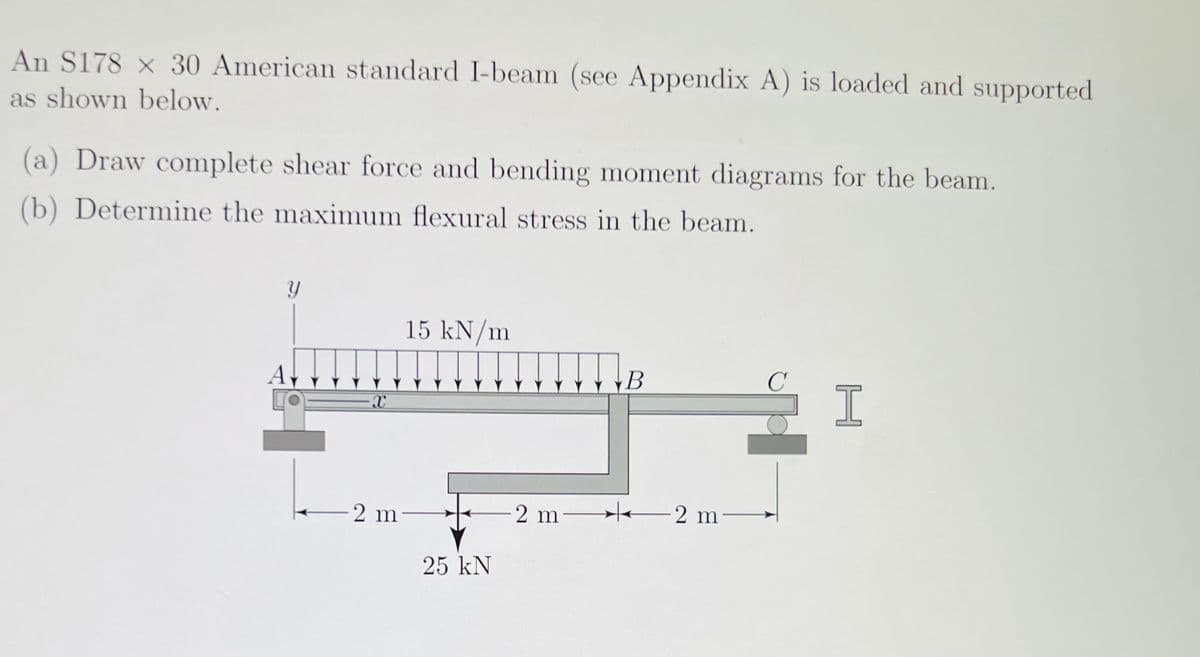
Transcribed Image Text:An S178 x 30 American standard I-beam (see Appendix A) is loaded and supported
as shown below.
(a) Draw complete shear force and bending moment diagrams for the beam.
(b) Determine the maximum flexural stress in the beam.
y
A
X
15 kN/m
2 m-
25 kN
-2 m-
B
2 m-
C
I
Expert Solution
This question has been solved!
Explore an expertly crafted, step-by-step solution for a thorough understanding of key concepts.

This is a popular solution!

Trending now
This is a popular solution!

Step by step
Solved in 3 steps with 3 images

Knowledge Booster


Learn more about
Need a deep-dive on the concept behind this application? Look no further. Learn more about this topic, mechanical-engineering and related others by exploring similar questions and additional content below.Recommended textbooks for you
Mechanics of Materials (MindTap Course List)
Mechanical Engineering
ISBN:
9781337093347
Author:
Barry J. Goodno, James M. Gere
Publisher:
Cengage Learning
Mechanics of Materials (MindTap Course List)
Mechanical Engineering
ISBN:
9781337093347
Author:
Barry J. Goodno, James M. Gere
Publisher:
Cengage Learning