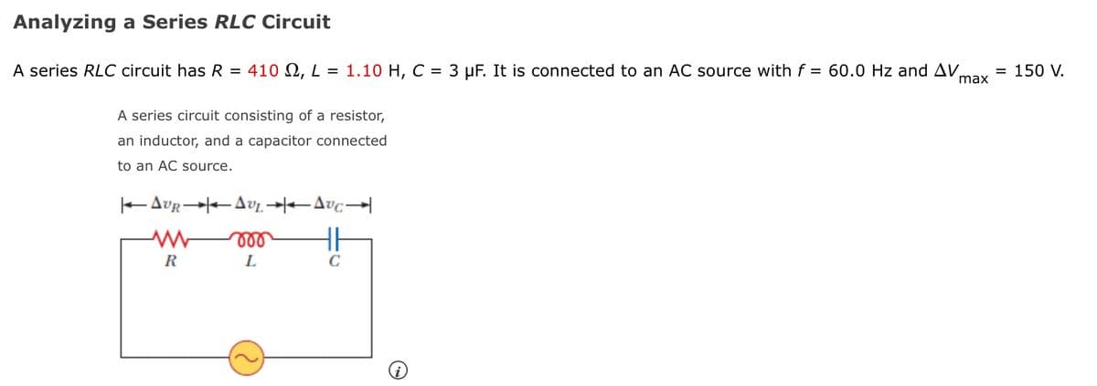
Analyzing a Series RLC Circuit A series RLC circuit has R = 410 2, L = 1.10 H, C = 3 µF. It is connected to an AC source with f = 60.0 Hz and AV = 150 V. max A series circuit consisting of a resistor, an inductor, and a capacitor connected to an AC source. EAUR AvL -Avc all R
Analyzing a Series RLC Circuit A series RLC circuit has R = 410 2, L = 1.10 H, C = 3 µF. It is connected to an AC source with f = 60.0 Hz and AV = 150 V. max A series circuit consisting of a resistor, an inductor, and a capacitor connected to an AC source. EAUR AvL -Avc all R

Chapter14: Inductance
Section: Chapter Questions
Problem 14.8CYU: Check Your Understanding (a) If the current in the circuit of in Figure 14.12(b) increases to 909 of...

Related questions
Question
Transcribed Image Text:Analyzing a Series RLC Circuit
A series RLC circuit has R = 410 N, L = 1.10 H, C = 3 µF. It is connected to an AC source with f = 60.0 Hz and AV,
max
150 V.
A series circuit consisting of a resistor,
an inductor, and a capacitor connected
to an AC source.
ll
R
L
C
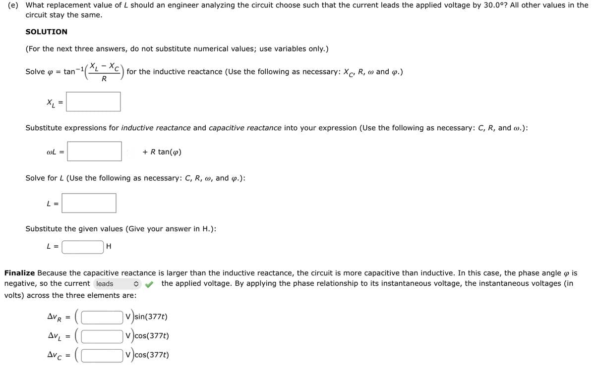
Transcribed Image Text:(e) What replacement value of
circuit stay the same.
should an engineer analyzing the circuit choose such that the current leads the applied voltage by 30.0°? All other values in the
SOLUTION
(For the next three answers, do not substitute numerical values; use variables only.)
-1
7.
Solve o
tan
for the inductive reactance (Use the following as necessary: Xc, R, w and o.)
R
X =
Substitute expressions for inductive reactance and capacitive reactance into your expression (Use the following as necessary: C, R, and w.):
wL =
+ R tan(o)
Solve for L (Use the following as necessary: C, R,
W,
and p.):
L =
Substitute the given values (Give your answer in H.):
L =
H
Finalize Because the capacitive reactance is larger than the inductive reactance, the circuit is more capacitive than inductive. In this case, the phase angle o is
negative, so the current leads
the applied voltage. By applying the phase relationship to its instantaneous voltage, the instantaneous voltages (in
volts) across the three elements are:
j
v )sin(377t)
AVR
AVL
V )cos(377t)
Avc =
v cos(377t)
Expert Solution
This question has been solved!
Explore an expertly crafted, step-by-step solution for a thorough understanding of key concepts.

Step by step
Solved in 5 steps with 5 images

Knowledge Booster


Learn more about
Need a deep-dive on the concept behind this application? Look no further. Learn more about this topic, physics and related others by exploring similar questions and additional content below.Recommended textbooks for you