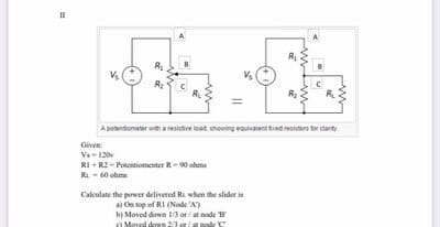
Ap eat hong ttede rca Given V-12 RI - R2-Pentio Calelate the power deliverod R when the slider is On upof RI (Nade A) b Moved down 0 e ode down 23ar/apode


Q: Three resistors havmg dimic valne 1hat are, respectively, 1. 1rand ik dums are Cmnected m serias to…
A: The current =120/(9K+12.5K+1K) =5.3mA
Q: Problem 2 De ter mne io,t02, Uo, Vn for the following cirenits the 0,7V Constant voltage model for…
A: The diode will conduct only during the forward bias and it can be replaced by its equivalent voltage…
Q: Qs b) Calculate Vo in Figure 26 whing naled andiyds. 20n SOMF (0mH (D gin (l0$E -907, 4i 2012
A: According to question: The frequency in rad/s is given as ω=1000rad/s The given circuit becomes…
Q: EX.5 Fer the current filament of fig. calculate Hat :- ® (4,0,-3). Z 4 1o A loA mA Ans:- @ -79.58(ã+…
A: For the current filament in Y-direction, When the conductor is semi-infinite, so that point A is now…
Q: Referring to this figure, calculate Zo for VGS = -3.2 V. express answer in ohms Vp in the figure is…
A: The given circuit diagram is shown below: It is given that: IDSS=16 mA=16×10-3 AVP=-4 Vyon=25…
Q: Ven: 2102-1ov nd VAN Ê VenN i4) Sequen ce 26) sequenee
A: In this question we will find VAN and VBN for positive and negative sequence....
Q: Determine Rout (in kl2) for the figure. Ipss= 10 mA Vp=-4 V 4.7 kM 10 V o M Mw0-2.5 V 2 ΜΩ
A: We need to find out output impedance of given circuit
Q: The force betwoen two straight canductors increases when O distance between them increases o…
A: When two current-carrying conductors are placed near to each other it experiences a force. If the…
Q: 37- Which one of the expressions is the correct form of Faraday's law in general? O A) $B-ds=,I B)…
A: Self Inductance of coil: The behavior of a current-carrying coil that resists or opposes the change…
Q: TG Fon the cineuit given in the Figune fo rn problem 2 () Calc ulate the value of RL fon which it…
A: Given circuit is =
Q: +1,0V +36 slokn 5.6kn B = 50, assume VBE) = 0.8V fina VE, VC, VB 1E, ib, ic
A:
Q: SPheres hauesta conducting charges .147 pC an T.851 pC sthy are two Hentiaal Conduc tiy Brought Ynto…
A: In this question we are given two charges . And when they came in contact , the charge is…
Q: 16 Volt Ri = 1oka Rc= 3K-2 B=100 Vz-10 Volt Find: Is, Ie.Ie, Ve .VCE .VEIVB,I, Pz
A: The solution is given.
Q: Ex. 140. Assume all mks units in Figure 140. Determine the loop currents: I1, 12, 13 when V1=-7, V2=…
A: This question belongs to circuit theory . It is based on the concept of mesh analysis in the circuit…
Q: Determine the approximate value of lp of Figure 522. VDD 17V 1.8kQ V, = 9.8V O 3.67 MA 4 mA 7 mA…
A: In this question, We need to choose the correct options What is drain current?
Q: ferminals a' & Compuie the equivalent rehistenn ce the i eircuita. values l or frachimo) toro ughout…
A: We are authorized to answer one question at a time, since you have not mentioned which question you…
Q: ) Eaglain why would be gret shorage d electrical ereryy beneft CLonoMic to power syotems.
A: As per bartleby expert policy, only first individual question is to be answered. Kindly repost…
Q: 054A2 32-4 A YA Calculak Hte Cupent Hsalgh He 32-2 resister and its drection Using 1Lévenink Heurem.
A:
Q: The maximum power that can be generated by a wind turbine is called. Select one: O lock-in Power…
A: The cut-in speed (ordinarily somewhere in the range of 6 and 9 mph) is the point at which the edges…
Q: Desian arablem for ryrdelta ransfarmations Dtrmink the eauivalent resistance hetwreen the terminals…
A: This circuit has series and parallel resistances. Find the Resistance RAB we are solving this…
Q: امقای شهرعه مؤهلين Qu: Aind the vetue of R and IT the Rog=2-354 4, tox itw Q b Difine the electricaf…
A: In this problem let us try to find out the value of R and also the current IT using the network…
Q: Given the information appearing in Figure beside (assume Ic=Ig) determine: (а) Iс. (b) VẸ. (c) VB-…
A: Disclaimer: Since you have asked multipart questions, we will solve the first three subpart for…
Q: Question 3: What is the change on current on each branch if the angular frequency (@) of the voltage…
A:
Q: LM 117 VIN-28V VIN VOUT VOUT R2 is half as much as R1 and Vref is 2V. ADJ R1 240 Vref ladj 11 C2…
A: We will find out current and resistor
Q: ZI,Zo, AVA Q1. find re 8 V 3.6 kN 1 ko B = 70 HE 4 ko -5 V
A: 3.6 kΩ×IC=8 VIC=2.2 mA collector current,IC=β IBso, base current,IB=ICβ=2.270IB=31.4 mA we know,…
Q: Home Workse P1 Two resistors must beselected.so that the cunnt in one is our times the cucent in the…
A: Given data The given value of equivalent resistance Req = 5kΩ For calculating the value R1 and R2 we…
Q: of trensis tor are :-17 Q:Bre hie = 2k2, hfe=50 - parameters The hoftansis tor are = 50kn thoe=…
A:
Q: Shorl Shunl Comppound Generalor delivess Ioad Curient ol 30 A al d has armatnie, Senes field & Shunl…
A:
Q: Question Five 10 V Given that the FET shown in figure 3 has Inss-8mA and a Vp 4V. 10MO 1KO Calculate…
A:
Q: RE : 3,3 k 14,7ks IMa 15042 : IMa Nc VBE =0.7V 3.3lu VAG, VAE, VCE If B=60 dekrmire Vec.
A:
Q: What resistance must be added in parallel with 40 and 10 ohms to produce a total current of 15 amps?
A: Calculate equivalent resistance of the circuit
Q: 4- poke, dong- hent Com pound A genenaton valtege supplies 100A at a termenal 500v. nexistanee is…
A: Generated emf = terminal voltage +voltage drop in armature resistance and series field resistance +…
Q: 8. Deteamine the current it) Howing Thoougth the serjes RL ciocuit shoun in figuse when the Sinewave…
A: The given circuit is series R-L circuit. The input voltage is Vin(t)=10sin25t. When switch is closed…
Q: Q4) The following graople is showing 0.5MF cupucitdoe. Cole lyte groph the copecitoa voltge of a the…
A: The voltage waveform across the capacitor is shown in the figure. Find the current waveform in…
Q: 2 For the Circust below, solue for ix(€). 4 S2 ..బ 18ix 25 V Lix * the switch openo at -100
A: The given circuit diagram is: The switch opens at t = 0, that is before t = 0 the circuit was in…
Q: 3. A 1-d Sul Conviester, Conneeted to 230 v, so M. Sousre . feedng a loael R: 10 n n series wish a…
A:
Q: 2 k 18 V 4kN 2kN 4 kn 4kΩ ww 3mA 3mA 1kn
A:
Q: The resistance R of a conductor is EA (A) Je EJ (B) Al El (C) JA JA (D) El
A: The resistance of a conductor is R=ρlA ..... (1) here, ρ is resistivityl is lengthA is area of…
Q: то Apply mason Rule (SGP) to block diegion below. * Git @ e(s) pe ((S) 6123 LEH H₁ H₂t
A: As per company guidelines we are supposed to answer only one question. Kindly repost other questions…
Q: IRON CORE z direchion N= 100 1-ムA d-10cm air gp winling A toroidal 1ron cor e with alr gap systern…
A: As our guide lines I solved only 3 subparts. Remaining parts are post separately.
Q: bExamplelonim The Given the following circuit, find the value of the voltage source and the power…
A:
Q: Calulate the Conduetvity of pure G lian at room termpeuhfure when the Cencentraton o Corries is on…
A: The conductivity of the pure silicon at room temperature is determined as shown below
Q: Jn the giun cirauit, what resistor RL uill absorb maimum pouer and what is this poser? RL is equal…
A: In this circuit question we have to determine the value of RL so that it will absorb maximum power…
Q: Dawvre, avve, Suppose you have two point charges each of 79 nC. Ananya Ananya daveicloud.com xpertta…
A: The value of the first charge is, q1=79 nC The value of the first charge is, q2=79 nC Since the…
Q: iGiven 60 uC point charge located at ongin, the total electric Aux through as spnere r-26cm o plane…
A: Total electric flux coming out of a closed surface is equal to charge inside the closed surface.…
Q: write the state equadion-far the networ.k. ShawAbelow Ust) () loope (voy 2
A:
Q: Q1/ check the signal below : (energy or power) X(t) = e2at u(-t) * 1 Add file
A: As per the guidelines of Bartleby we supposed to answer first question only for solution of…
Q: 330ka 470RO 47hD 12mv 470 18mVph (a) 6kO 9V Vi-8 sin800at V 2kQ A6- (b) Figure (3)
A:
Q: A set of copper conductors on a branch circuit serve a water pump motor rated at 20A. The pump is…
A:

Step by step
Solved in 4 steps with 4 images

- In the circuit given in the figure | VBE | = 0.7V, R1 = 34.65Kohm, R2 = 118.04Kohm, RC = 1.32Kohm, RE = 3.97Kohm, VCC = -12.00V, Beta = 287.00, calculate IC current with full analysis.Lrocedure A- Kirchhoff's voltage law: The circuit in Figure 2 will be used o test the valdity of Kirchhoffs voltage law, Figure (2) Construct the circuit as shown in the figure (2). Measure the power supply output voltage and the potential drops across each of the thrae resistors. Record these measurements in your lab notebook as in the following table: University of Ti-Qar/ Departmnt of Elctricl aad Fectronlc Enginearing / Prepared by M 5¢ Al Karvem Soes 1+ Stage: Fundamentals of Flectrical Engineering | Lob 3 - Kirchhoff's Laws. 201520, Table 1; data collected for testing the validity of Kirchhot?s voltage law. 3)From your experimental data (table 2), calculate the total current into the node point P. Now calculate the total current out of the node point P along with its uncertainty. Does the current into the node agree with the current out of the node within experimental uncertainty?Q2 / For the circuit shown, what is the maximum power transferred to the load impedance Z1? 200 j100 500 a ANV AN~ l - + 5008V @ 00av, (1) -0 =] Tt e
- Identify the equation that proves Kirchhoff's Voltage Law for the circuit below given the following:ES1 = 8 V, ES2 = 14 V, R1 = 12 Ω, R2= 10 Ω, R3 = 22 Ω, and IT = 0.5 AUsing Kirchoff's voltage law to determine the unknown voltage E2 for the configuration given in the figure below. Given that: - The source E1= 110 VV, - V1= 23.5 V, V2= 18 V, V3= 16.4 V, and V4= 20.5 VIn the circuit in Figure 2, the capacitor and The circuit of resistance is defined as a load circuit. A) Find the average power dissipated by the load circuit. B) How much of the average power calculated in a) by the resistance in the load circuit and how much spent by the capacitor? Comment on the results obtained? c) In the circuit in Figure 2, with a resistance of 80 Ω 2/3π H coil of is connected in series. In this case, Calculate the transformer ratio (n) to optimize power distribution to the load? Obtained comment on the result? D) Calculate the complex power and reactive power dissipated by the load in the newly created circuit.
- The voltage source V1= 200 V with internal resistance R1=1 in Figure 2.1 will feed the resistive resistor RL with a transformer with a conversion ratio of 10 and considered ideal. What should be the value (RL=?) of the RL resistor to be placed so that the RL resistor can draw maximum power from the voltage source? What is the power consumed by the voltage source (Pv1=?) when the RL resistor you found is active? In this case, how much power (PRL=?) is wasted on the resistor RL you found? Calculate your solutions legibly and write the results you find inside by drawing a box as below.Using Kirchoff's voltage law to determine the unknown voltage V3 for the configuration given in the figure below. Given that: - The source E= 90 V, - V1= 10 VV and V2= 10.3 VV.1) Use the superposition principle to determine the current in the load resistance RL, in the dc circuit of Figure QA1(a) 2) The current through a pure capacitor is given byi = 28.28cos(314t).Derive an expression for the voltage across the capacitor in the form v = Vm cos(wt) and comment on your answer. 3)Estimate the value of the current I and the voltage V in each of the circuits shown in Figure QA1(c) and justify your method of estimation.