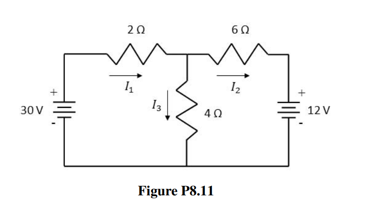
Apply Kirchhoff’s laws to the resistive circuit shown in Figure P8.11 to generate two sets of simultaneous linear equations. Show that the set of equations generated from applying Kirchhoff’s Voltage Law to the left and right loops and the set of equations generated from applying Kirchhoff’s Voltage law to the left and outer loops yields the same solution for the value of the currents I1, I2, and I3. a. To generate the first set of equations, write three equations correspon- ding to: 1. current law at a junction, 2. voltage law around the left loop, and 3. voltage law around the right loop. b. To generate the second set of equations, write three equations corre- sponding to: 1. current law at a junction, 2. voltage law around the left loop, and 3. voltage law around the outer loop.

Apply Kirchhoff’s laws to the resistive circuit shown in Figure P8.11 to generate two sets of simultaneous linear equations. Show that the set of equations generated from applying Kirchhoff’s Voltage Law to the left and right loops and the set of equations generated from applying Kirchhoff’s Voltage law to the left and outer loops yields the same solution for the value of the currents I1, I2, and I3.
a. To generate the first set of equations, write three equations correspon-
ding to:
1. current law at a junction,
2. voltage law around the left loop, and
3. voltage law around the right loop.
b. To generate the second set of equations, write three equations corre-
sponding to:
1. current law at a junction,
2. voltage law around the left loop, and
3. voltage law around the outer loop.


Trending now
This is a popular solution!

Step by step
Solved in 3 steps with 2 images
