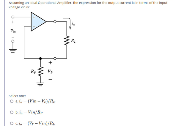
Assuming an ideal Operational Amplifier, the expression for the output current io in terms of the input voltage vin is:
Assuming an ideal Operational Amplifier, the expression for the output current io in terms of the input voltage vin is:

Chapter25: Television, Telephone, And Low-voltage Signal Systems
Section25.1: Television Circuit
Problem 5R: From a cost standpoint, which system is more economical to install: a master amplifier distribution...

Related questions
Question
circuit
Transcribed Image Text:Assuming an ideal Operational Amplifier, the expression for the output current io in terms of the input
voltage vin is:
Vin
RL
+
RF
VF
Select one:
O a. i, = (Vin – Vf)/Rf
O b. i, = Vin/RF
O c.i, = (Vp – Vin)/RL
Expert Solution
This question has been solved!
Explore an expertly crafted, step-by-step solution for a thorough understanding of key concepts.

This is a popular solution!

Trending now
This is a popular solution!

Step by step
Solved in 2 steps

Follow-up Questions
Read through expert solutions to related follow-up questions below.
Follow-up Question
What is the output impedance seen by RL?
Transcribed Image Text:DMC DMCANA607 WrittenAssessment
Sphumelele Zikalala 2
Me.
Design Layout
References
Mailings
Help
Table Design Layout
四四|,些, = z
Styles
ri (Body)
I U v ab x, x Ao
Dictate
Editor
A A"
******
Font
Paragraph
Voice
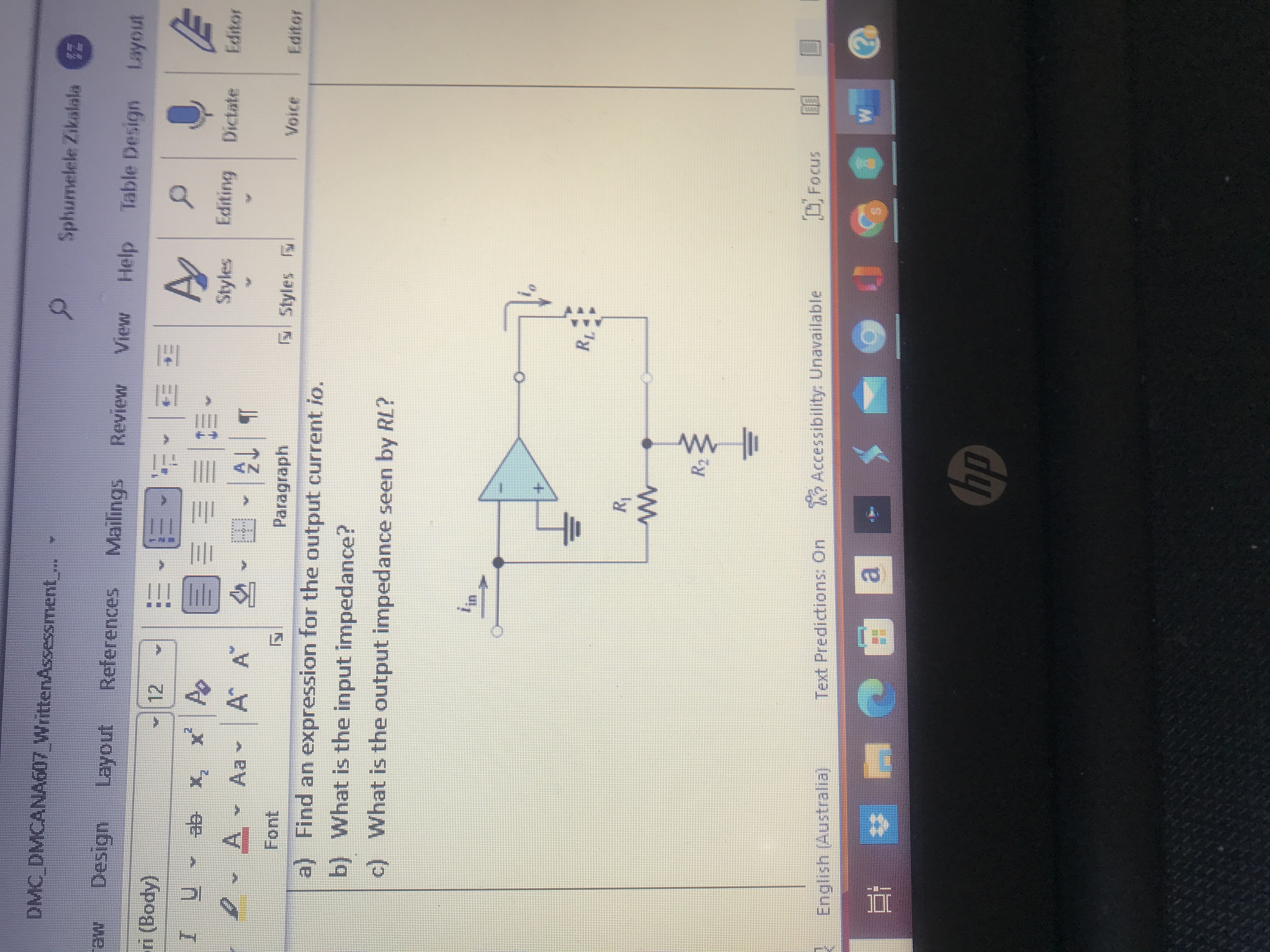
a) Find an expression for the output current io.
b) What is the input impedance?
c) What is the output impedance seen by RL?
Accessibility Unavailable
團
Text Predictions: On
English (Australia).
dy
Solution
Knowledge Booster


Learn more about
Need a deep-dive on the concept behind this application? Look no further. Learn more about this topic, electrical-engineering and related others by exploring similar questions and additional content below.Recommended textbooks for you
EBK ELECTRICAL WIRING RESIDENTIAL
Electrical Engineering
ISBN:
9781337516549
Author:
Simmons
Publisher:
CENGAGE LEARNING - CONSIGNMENT
EBK ELECTRICAL WIRING RESIDENTIAL
Electrical Engineering
ISBN:
9781337516549
Author:
Simmons
Publisher:
CENGAGE LEARNING - CONSIGNMENT