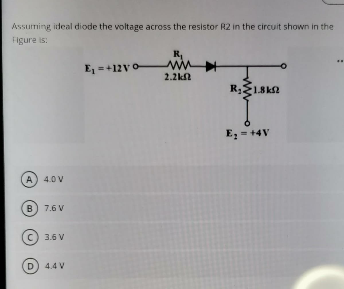
Assuming ideal diode the voltage across the resistor R2 in the circuit shown in the Figure is: R1 E1 = +12V0- 2.2k2 R,E1.8kN E, = +4V A 4.0 V 7.6 V 3.6 V D 4.4 V


Analysis of Diode
It is a semiconductor device in electronics applications where only a one-way current is required. It is like a one-way switch that allows current to flow in one direction only. A diode has two terminals, a cathode, and an anode. The cathode is the negative terminal that carries electrons, while the anode is the positive terminal that carries holes. Although no element has holes, it just means that there is a free space for electrons. Diodes are used to convert AC to DC. As we know, AC shifts between positive and negative cycles and DC stays positive constantly. As the diodes allow current only in one direction, they filter out the AC signal’s negative cycle and only keep the positive one.
Working and Construction
In civil engineering, construction means the application of principles of science and mathematics for building bridges, dams, buildings, roads, highways, tunnels, airports, structures, etc. Different branches of science, like physics and chemistry, are extensively applied to design and analysis in construction. Material properties, the science of atmospheric conditions (like solutions, mixtures, etc.), the impact of environmental factors like, corrosion and acidity are some of the primary knowledge of chemistry which are used by civil engineers to carry out construction. Estimation of forces, application of laws of mechanics, fluids mechanics, soil mechanics, etc. are some of the fundamental concepts of physics, which are well applied in construction works. Building construction and structural engineering are two of the most primary areas in civil engineering that parallelly applies principles of both chemistry and physics to carry on construction works.
Property of Diode
An electronic component that facilitates the directional flow of current is known as a diode. According to the direction of the flow of current, the resistance of a diode changes from zero to Infinity.

Step by step
Solved in 2 steps with 2 images


