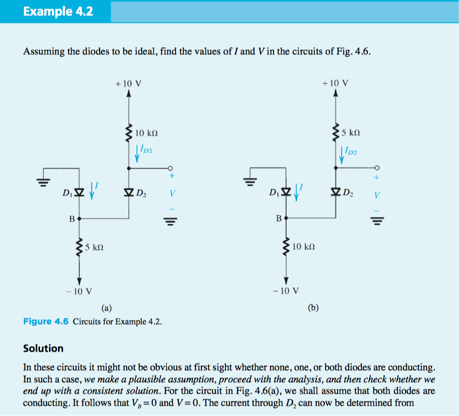
Assuming the diodes to be ideal, find the values of I and V in the circuits of Fig. 4.6. + 10 V + 10 V 10 kM 5 k. V B 5 kM 10 kΩ - 10 V - 10 V (a) (b) Figure 4.6 Circuits for Example 4.2. Solution In these circuits it might not be obvious at first sight whether none, one, or both diodes are conducting. In such a case, we make a plausible assumption, proceed with the analysis, and then check whether we end up with a consistent solution. For the circuit in Fig. 4.6(a), we shall assume that both diodes are conducting. It follows that V, = 0 and V= 0. The current through D, can now be determined from
Assuming the diodes to be ideal, find the values of I and V in the circuits of Fig. 4.6. + 10 V + 10 V 10 kM 5 k. V B 5 kM 10 kΩ - 10 V - 10 V (a) (b) Figure 4.6 Circuits for Example 4.2. Solution In these circuits it might not be obvious at first sight whether none, one, or both diodes are conducting. In such a case, we make a plausible assumption, proceed with the analysis, and then check whether we end up with a consistent solution. For the circuit in Fig. 4.6(a), we shall assume that both diodes are conducting. It follows that V, = 0 and V= 0. The current through D, can now be determined from

Introductory Circuit Analysis (13th Edition)
13th Edition
ISBN:9780133923605
Author:Robert L. Boylestad
Publisher:Robert L. Boylestad
Chapter1: Introduction
Section: Chapter Questions
Problem 1P: Visit your local library (at school or home) and describe the extent to which it provides literature...

Related questions
Question
Transcribed Image Text:Example 4.2
Assuming the diodes to be ideal, find the values of I and V in the circuits of Fig. 4.6.
+ 10 V
+ 10 V
10 kN
5 kN
D,
ZD2
V
B
5 kN
10 kn
- 10 V
- 10 V
(a)
(b)
Figure 4.6 Circuits for Example 4.2.
Solution
In these circuits it might not be obvious at first sight whether none, one, or both diodes are conducting.
In such a case, we make a plausible assumption, proceed with the analysis, and then check whether we
end up with a consistent solution. For the circuit in Fig. 4.6(a), we shall assume that both diodes are
conducting. It follows that V, = (0 and V=0. The current through D, can now be determined from
Transcribed Image Text:4.38 Solve the problems in Example 4.2 using the constant-
voltage-drop (V,= 0.7 V) diode model.
Expert Solution
This question has been solved!
Explore an expertly crafted, step-by-step solution for a thorough understanding of key concepts.

This is a popular solution!

Trending now
This is a popular solution!

Step by step
Solved in 2 steps with 2 images

Recommended textbooks for you
Introductory Circuit Analysis (13th Edition)
Electrical Engineering
ISBN:
9780133923605
Author:
Robert L. Boylestad
Publisher:
PEARSON

Delmar's Standard Textbook Of Electricity
Electrical Engineering
ISBN:
9781337900348
Author:
Stephen L. Herman
Publisher:
Cengage Learning

Programmable Logic Controllers
Electrical Engineering
ISBN:
9780073373843
Author:
Frank D. Petruzella
Publisher:
McGraw-Hill Education
Introductory Circuit Analysis (13th Edition)
Electrical Engineering
ISBN:
9780133923605
Author:
Robert L. Boylestad
Publisher:
PEARSON
Delmar's Standard Textbook Of Electricity
Electrical Engineering
ISBN:
9781337900348
Author:
Stephen L. Herman
Publisher:
Cengage Learning
Programmable Logic Controllers
Electrical Engineering
ISBN:
9780073373843
Author:
Frank D. Petruzella
Publisher:
McGraw-Hill Education

Fundamentals of Electric Circuits
Electrical Engineering
ISBN:
9780078028229
Author:
Charles K Alexander, Matthew Sadiku
Publisher:
McGraw-Hill Education

Electric Circuits. (11th Edition)
Electrical Engineering
ISBN:
9780134746968
Author:
James W. Nilsson, Susan Riedel
Publisher:
PEARSON

Engineering Electromagnetics
Electrical Engineering
ISBN:
9780078028151
Author:
Hayt, William H. (william Hart), Jr, BUCK, John A.
Publisher:
Mcgraw-hill Education,