
Structural Analysis
6th Edition
ISBN: 9781337630931
Author: KASSIMALI, Aslam.
Publisher: Cengage,
expand_more
expand_more
format_list_bulleted
Related questions
Concept explainers
Question
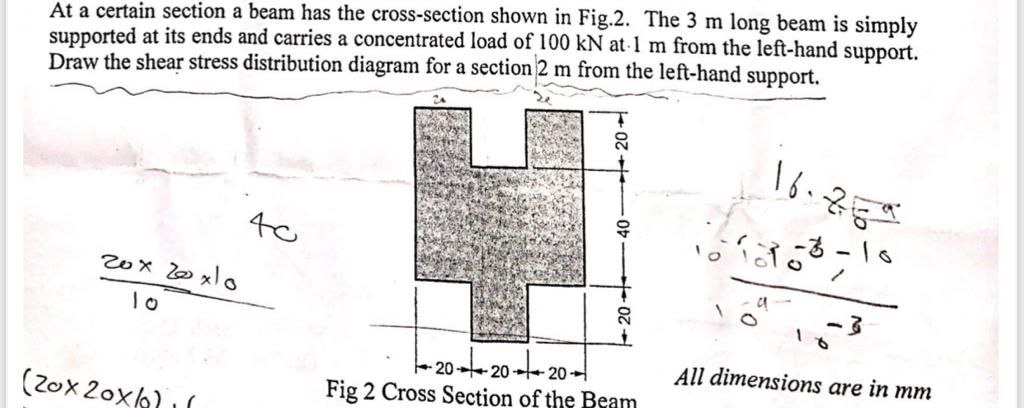

Transcribed Image Text:At a certain section a beam has the cross-section shown in Fig.2. The 3 m long beam is simply
supported at its ends and carries a concentrated load of 100 kN at 1 m from the left-hand support.
Draw the shear stress distribution diagram for a section 2 m from the left-hand support.
20x20x10
10
(20x20x1
40
20-
-20-20-20-
Fig 2 Cross Section of the Beam
16.29
All dimensions are in mm
Expert Solution
This question has been solved!
Explore an expertly crafted, step-by-step solution for a thorough understanding of key concepts.

Step by stepSolved in 4 steps with 4 images

Knowledge Booster


Learn more about
Need a deep-dive on the concept behind this application? Look no further. Learn more about this topic, civil-engineering and related others by exploring similar questions and additional content below.Similar questions
- (b) The beam is subjected to the loading shown in Fig. Q2(b), where P = 7 kN. Determine the average shear stress developed in the nails within region AB of the beam. The nails are located on each side of the beam and are spaced 100 mm apart. Each nail has a diameter of 5 mm. Hint: q VQ 9 T VQ It A 2 m 100 mm 30 mm 13 kN B -2 m 30 mm Fig. Q2(b) P 30 mm 250 mm 30 mm 150 mmarrow_forwardHow would you draw the deformation sketch?arrow_forwardGiven the beam shown in Fig. E2, answer the questions below. | 275 kN | 275 kN A 1.5m 1.8m 1.8m Fig. E2 (i) Knowing that o all = 160 MPa and Tall = 100 MPa select the most economical metric wide-flange shape that should be used to support the loading shown. (ii) Determine the value expected for the normal stress at the junction of the flange and the web of the selected beam. (iii) Determine the value expected for the shear stress at the junction of a flange and the web of the selected beam. (iv) Draw the stress element, and indicate the normal and shear stresses, for a point located at the junction of a flange and the web of the selected beam. (v) Draw the Mohr's Circle for the stress element determined in (iv). (vi) For the stress element in (iv), calculate the major principal stress o1 and the minor principal stress o3arrow_forward
- The beam shown in Fig1.carries a concentrated load of W and a total distributed load of 8 W. Determine the maximum safe value W that will not exceed allowable stresses in tension of 60 MPa, in compression of 90 MPa, or in shear of 15 MPa. 1m W ᎦᎳ ? 15 2m 1m 20mm Fig.1 140mm 20mm 2 20mm 140mmarrow_forwardshow all work clearly organizedarrow_forward
arrow_back_ios
arrow_forward_ios
Recommended textbooks for you
 Structural Analysis (10th Edition)Civil EngineeringISBN:9780134610672Author:Russell C. HibbelerPublisher:PEARSON
 Principles of Foundation Engineering (MindTap Cou...Civil EngineeringISBN:9781337705028Author:Braja M. Das, Nagaratnam SivakuganPublisher:Cengage Learning
 Fundamentals of Structural AnalysisCivil EngineeringISBN:9780073398006Author:Kenneth M. Leet Emeritus, Chia-Ming Uang, Joel LanningPublisher:McGraw-Hill Education
 Traffic and Highway EngineeringCivil EngineeringISBN:9781305156241Author:Garber, Nicholas J.Publisher:Cengage Learning
Structural Analysis (10th Edition)
Civil Engineering
ISBN:9780134610672
Author:Russell C. Hibbeler
Publisher:PEARSON
Principles of Foundation Engineering (MindTap Cou...
Civil Engineering
ISBN:9781337705028
Author:Braja M. Das, Nagaratnam Sivakugan
Publisher:Cengage Learning
Fundamentals of Structural Analysis
Civil Engineering
ISBN:9780073398006
Author:Kenneth M. Leet Emeritus, Chia-Ming Uang, Joel Lanning
Publisher:McGraw-Hill Education
Traffic and Highway Engineering
Civil Engineering
ISBN:9781305156241
Author:Garber, Nicholas J.
Publisher:Cengage Learning