At what frequency is the phase shift introduced by the circuit of Example 6.7 equal to -10 degrees.
At what frequency is the phase shift introduced by the circuit of Example 6.7 equal to -10 degrees.

Introductory Circuit Analysis (13th Edition)
13th Edition
ISBN:9780133923605
Author:Robert L. Boylestad
Publisher:Robert L. Boylestad
Chapter1: Introduction
Section: Chapter Questions
Problem 1P: Visit your local library (at school or home) and describe the extent to which it provides literature...

Related questions
Question
At what frequency is the phase shift introduced by the circuit of Example 6.7 equal to -10 degrees.
Transcribed Image Text:Known Quantities: R 1 k; C = 0.47 µF; vi(t) = 5 cos(@t) V.
be close to the ones computed above.
Find: The output voltage v.(t) at each frequency.
This low-pass filter would pass only the bass range of the audio spectrum.
EXAMPLE 6.7 Frequency Response of RC Low-Pass Filter
Compute the response of the RC filter of Figure 6.20 to sinusoidal inputs at the frequencies of
Analysis: In this problem, the input signal voltage and the frequency response of the circuit
cies. If the voltages are represented in phasor form, the frequency response can be used for
(equation 6.43) are known, and the output voltage must be found at two different frequen-
Part I
Circuits
347
Problem
LO
Compute
60 and 10,000 Hz.
the
mesponse of the RC filter of Figure 6.20 to sinusoidal inputs at the frequencies of
Solution
%3D
Assumptions: None.
calculation:
Vo
ja) = Hv (ja) =
Vi
%3D
1+ jwCR
V.(ja) = Hy(jw)V,(ja) =
1
V,(jw)
%3D
1+ jwCR
The cutoff frequency of the filter is wo = 1/RC = 2,128 rad/s such that the expression for the
%3D
frequency response in the form of equations 6.45 and 6.46 is:
1
1
|Hy (jw)| =
W
Hy (jw) =
%3D
%3D
1+ jw/wo
V1+ (@/@0)?
RA8.0
= - arctan
Wo
Next, recognize that at w = 60 Hz = 1207 rad/s, the ratio w/wo = 0.177. At w = 10,000 Hz =
20,000T, w/wo = 29.5. Thus, the output voltage at each frequency can be computed as
%3D
%3D
%3D
follows:
V,(@ = 27 60) =
1
V; (@ = 27 60) =
(0.985 x 5)Z-0.175 V
%3D
%D
%3D
1+ j0.177
V.(@ = 2n 10,000) =
1
V; (@ = 27 10,000) = (0.0339 × 5)2-1.537 V
%3D
%3D
%3D
1+ j29.5
And finally we write the time-domain response for each frequency:
v,(t) = 4.923 cos(27 60t – 0.175) V
at w = 2n 60 rad/s
%3D
o(t) = 0.169 cos(2n 10,000t - 1.537) V
at w = 27 10,000 rad/s
%3D
This Lo plots that only the low-frequency components of the signal are
of the audio spectrum.
passed by the filter.
be close to the ones
computed above.
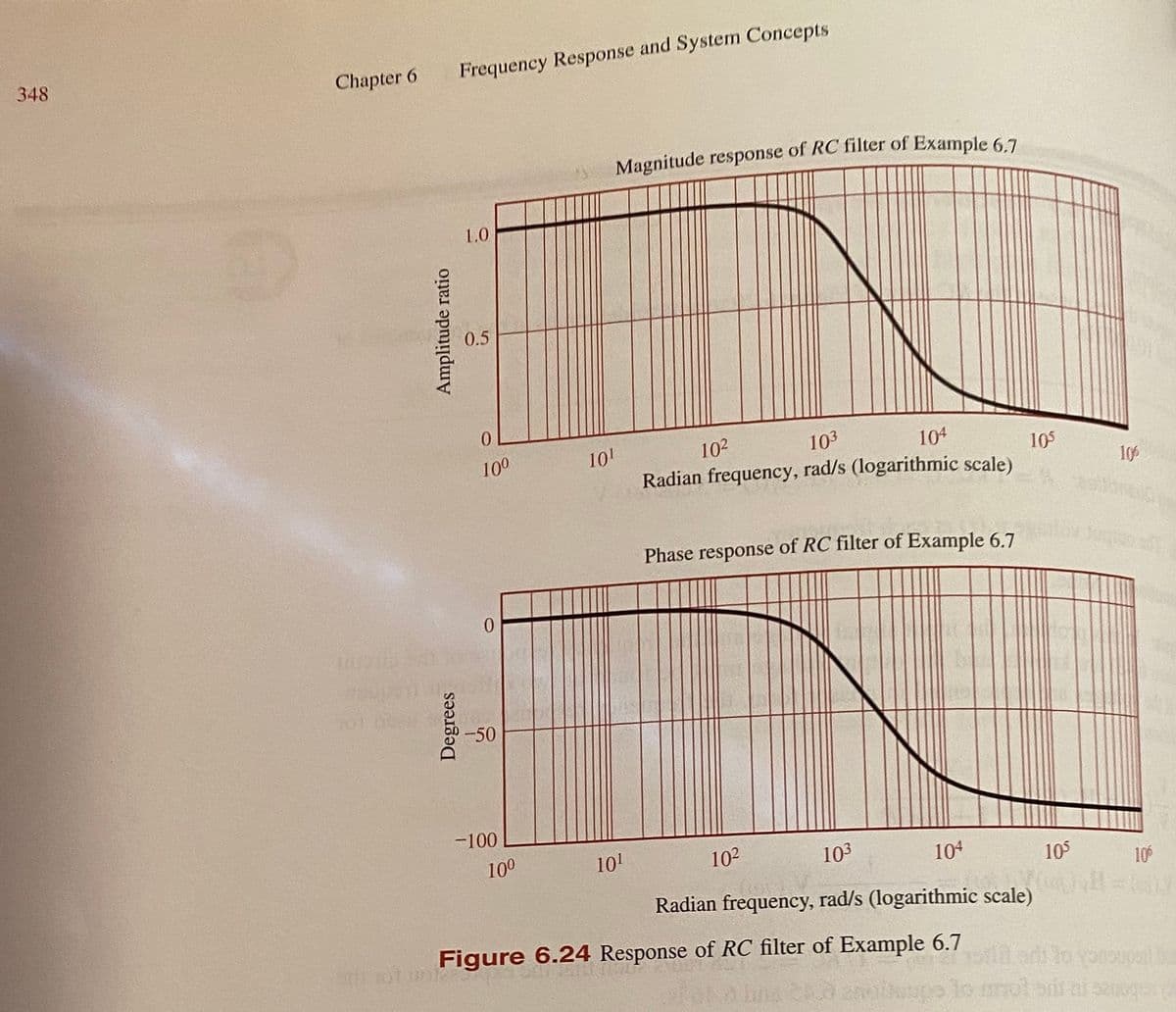
Transcribed Image Text:348
Frequency Response and System Concepts
Chapter 6
1.0
0.5
102
104
10
Radian frequency, rad/s (logarithmic scale)
100
103
105
106
Phase response
of RC filter of Example 6.7
-50
-100
100
101
102
103
104
105
10
Radian frequency, rad/s (logarithmic scale)
Figure 6.24 Response of RC filter of Example 6.7
proupal
lo mot
Degrees
Expert Solution
This question has been solved!
Explore an expertly crafted, step-by-step solution for a thorough understanding of key concepts.

Step by step
Solved in 2 steps with 1 images

Knowledge Booster


Learn more about
Need a deep-dive on the concept behind this application? Look no further. Learn more about this topic, electrical-engineering and related others by exploring similar questions and additional content below.Recommended textbooks for you
Introductory Circuit Analysis (13th Edition)
Electrical Engineering
ISBN:
9780133923605
Author:
Robert L. Boylestad
Publisher:
PEARSON

Delmar's Standard Textbook Of Electricity
Electrical Engineering
ISBN:
9781337900348
Author:
Stephen L. Herman
Publisher:
Cengage Learning

Programmable Logic Controllers
Electrical Engineering
ISBN:
9780073373843
Author:
Frank D. Petruzella
Publisher:
McGraw-Hill Education
Introductory Circuit Analysis (13th Edition)
Electrical Engineering
ISBN:
9780133923605
Author:
Robert L. Boylestad
Publisher:
PEARSON
Delmar's Standard Textbook Of Electricity
Electrical Engineering
ISBN:
9781337900348
Author:
Stephen L. Herman
Publisher:
Cengage Learning
Programmable Logic Controllers
Electrical Engineering
ISBN:
9780073373843
Author:
Frank D. Petruzella
Publisher:
McGraw-Hill Education

Fundamentals of Electric Circuits
Electrical Engineering
ISBN:
9780078028229
Author:
Charles K Alexander, Matthew Sadiku
Publisher:
McGraw-Hill Education

Electric Circuits. (11th Edition)
Electrical Engineering
ISBN:
9780134746968
Author:
James W. Nilsson, Susan Riedel
Publisher:
PEARSON

Engineering Electromagnetics
Electrical Engineering
ISBN:
9780078028151
Author:
Hayt, William H. (william Hart), Jr, BUCK, John A.
Publisher:
Mcgraw-hill Education,