Figure Q6 shows the cross-section of the typical layout of two tracks (A and B) on a printed circuit board with a ground plane C. The tracks are terminated as shown in the figure, with track A carrying digital signals. You can assume that the lines are electrically short. (a) Describe the electromagnetic coupling (crosstalk) between tracks A and B. (b) Draw the equivalent circuit that models the crosstalk and write down a relation between the voltage applied to track A and the voltage coupled on to track B at low frequencies, VNE.
Figure Q6 shows the cross-section of the typical layout of two tracks (A and B) on a printed circuit board with a ground plane C. The tracks are terminated as shown in the figure, with track A carrying digital signals. You can assume that the lines are electrically short. (a) Describe the electromagnetic coupling (crosstalk) between tracks A and B. (b) Draw the equivalent circuit that models the crosstalk and write down a relation between the voltage applied to track A and the voltage coupled on to track B at low frequencies, VNE.

Introductory Circuit Analysis (13th Edition)
13th Edition
ISBN:9780133923605
Author:Robert L. Boylestad
Publisher:Robert L. Boylestad
Chapter1: Introduction
Section: Chapter Questions
Problem 1P: Visit your local library (at school or home) and describe the extent to which it provides literature...

Related questions
Question
Transcribed Image Text:Continued overleaf
Page 4 of 5
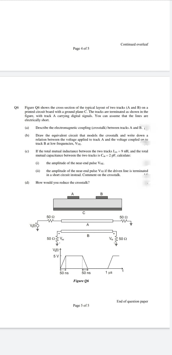
06
Figure Q6 shows the cross-section of the typical layout of two tracks (A and B) on a
printed circuit board with a ground plane C. The tracks are terminated as shown in the
figure, with track A carrying digital signals. You can assume that the lines are
electrically short.
(a)
Describe the electromagnetic coupling (crosstalk) between tracks A and B.
(b)
Draw the equivalent circuit that models the crosstalk and write down a
relation between the voltage applied to track A and the voltage coupled on to
track B at low frequencies, VNE.
(c)
If the total mutual inductance between the two tracks Lm = 9 nH, and the total
mutual capacitance between the two tracks is Cm = 2 pF, calculate:
(i)
the amplitude of the near-end pulse VNE-
(ii)
the amplitude of the near-end pulse VNE if the driven line is terminated
in a short circuit instead. Comment on the crosstalk.
(d)
How would you reduce the crosstalk?
B
C
50 2
50 2
V
A
B
50 Ων.
V. 50 2
Vt) 1
5V
50 ns
50 ns
1 us
Figure Q6
End of question paper
Page 5 of 5
Expert Solution
This question has been solved!
Explore an expertly crafted, step-by-step solution for a thorough understanding of key concepts.

Step by step
Solved in 3 steps with 2 images

Knowledge Booster


Learn more about
Need a deep-dive on the concept behind this application? Look no further. Learn more about this topic, electrical-engineering and related others by exploring similar questions and additional content below.Recommended textbooks for you
Introductory Circuit Analysis (13th Edition)
Electrical Engineering
ISBN:
9780133923605
Author:
Robert L. Boylestad
Publisher:
PEARSON

Delmar's Standard Textbook Of Electricity
Electrical Engineering
ISBN:
9781337900348
Author:
Stephen L. Herman
Publisher:
Cengage Learning

Programmable Logic Controllers
Electrical Engineering
ISBN:
9780073373843
Author:
Frank D. Petruzella
Publisher:
McGraw-Hill Education
Introductory Circuit Analysis (13th Edition)
Electrical Engineering
ISBN:
9780133923605
Author:
Robert L. Boylestad
Publisher:
PEARSON
Delmar's Standard Textbook Of Electricity
Electrical Engineering
ISBN:
9781337900348
Author:
Stephen L. Herman
Publisher:
Cengage Learning
Programmable Logic Controllers
Electrical Engineering
ISBN:
9780073373843
Author:
Frank D. Petruzella
Publisher:
McGraw-Hill Education

Fundamentals of Electric Circuits
Electrical Engineering
ISBN:
9780078028229
Author:
Charles K Alexander, Matthew Sadiku
Publisher:
McGraw-Hill Education

Electric Circuits. (11th Edition)
Electrical Engineering
ISBN:
9780134746968
Author:
James W. Nilsson, Susan Riedel
Publisher:
PEARSON

Engineering Electromagnetics
Electrical Engineering
ISBN:
9780078028151
Author:
Hayt, William H. (william Hart), Jr, BUCK, John A.
Publisher:
Mcgraw-hill Education,