(b) An industrial load is supplied through a transmission line that has a line impedance of 0.1 + j0.2 Q. The 60 Hz power line voltage at the load is 480 V (rms). The load absorbs 124 kW at a lagging power factor, pf of 0.75. (i) Calculate the total reactive power, Qı and apparent power, Si when pf is 0.75. Calculate the total reactive power, Q2 and apparent power, S2 when pf is raised to 0.9. (ii) (iii) Find the value of capacitance, C when placed in parallel with the load that will raise the pf to 0.9 lagging. (iv) Sketch a diagram of power triangle with complete labels that describes power
(b) An industrial load is supplied through a transmission line that has a line impedance of 0.1 + j0.2 Q. The 60 Hz power line voltage at the load is 480 V (rms). The load absorbs 124 kW at a lagging power factor, pf of 0.75. (i) Calculate the total reactive power, Qı and apparent power, Si when pf is 0.75. Calculate the total reactive power, Q2 and apparent power, S2 when pf is raised to 0.9. (ii) (iii) Find the value of capacitance, C when placed in parallel with the load that will raise the pf to 0.9 lagging. (iv) Sketch a diagram of power triangle with complete labels that describes power

Power System Analysis and Design (MindTap Course List)
6th Edition
ISBN:9781305632134
Author:J. Duncan Glover, Thomas Overbye, Mulukutla S. Sarma
Publisher:J. Duncan Glover, Thomas Overbye, Mulukutla S. Sarma
Chapter2: Fundamentals
Section: Chapter Questions
Problem 2.30MCQ: Under balanced operating conditions, consider the three-phase complex power delivered by the...

Related questions
Question
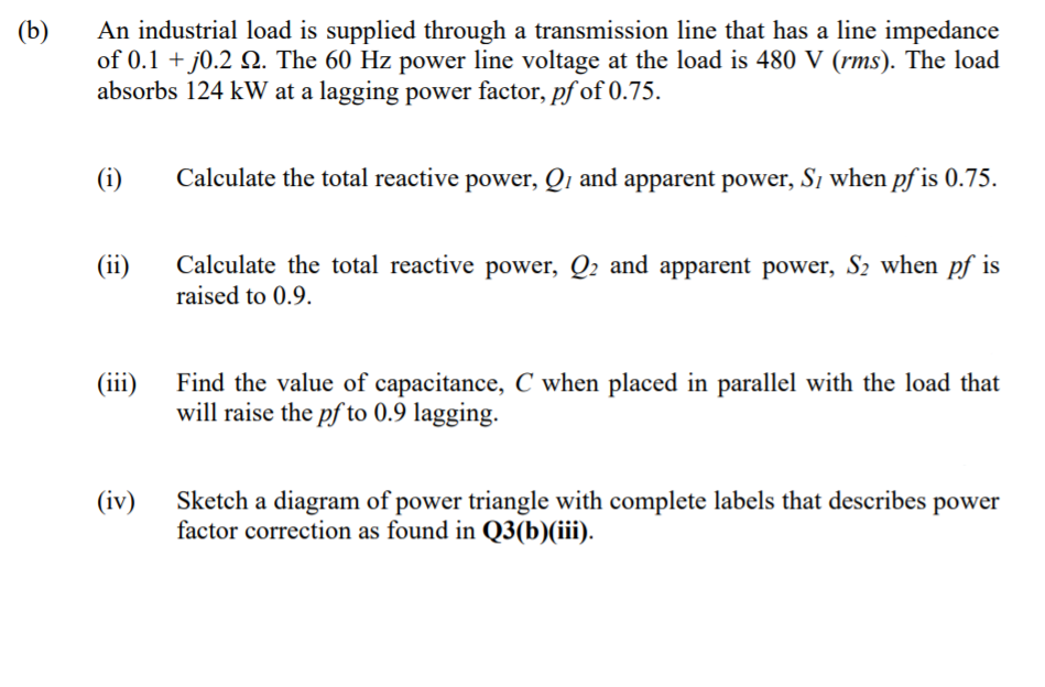
Transcribed Image Text:(b)
An industrial load is supplied through a transmission line that has a line impedance
of 0.1 + j0.2 Q. The 60 Hz power line voltage at the load is 480 V (rms). The load
absorbs 124 kW at a lagging power factor, pf of 0.75.
(i)
Calculate the total reactive power, Qı and apparent power, Si when pf is 0.75.
Calculate the total reactive power, Q2 and apparent power, S2 when pf is
raised to 0.9.
(ii)
(iii)
Find the value of capacitance, C when placed in parallel with the load that
will raise the pf to 0.9 lagging.
(iv)
Sketch a diagram of power triangle with complete labels that describes power
factor correction as found in Q3(b)(iii).
Expert Solution
This question has been solved!
Explore an expertly crafted, step-by-step solution for a thorough understanding of key concepts.

Step by step
Solved in 3 steps with 2 images

Knowledge Booster


Learn more about
Need a deep-dive on the concept behind this application? Look no further. Learn more about this topic, electrical-engineering and related others by exploring similar questions and additional content below.Recommended textbooks for you
Power System Analysis and Design (MindTap Course …
Electrical Engineering
ISBN:
9781305632134
Author:
J. Duncan Glover, Thomas Overbye, Mulukutla S. Sarma
Publisher:
Cengage Learning
Power System Analysis and Design (MindTap Course …
Electrical Engineering
ISBN:
9781305632134
Author:
J. Duncan Glover, Thomas Overbye, Mulukutla S. Sarma
Publisher:
Cengage Learning