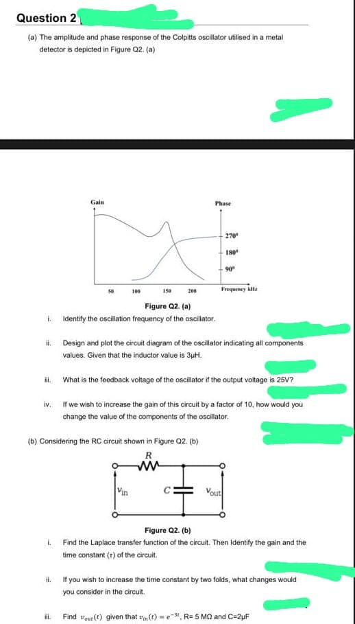
(b) Considering the RC circuit shown in Figure Q2. (b) R L Vin iii. Vout Figure Q2. (b) Find the Laplace transfer function of the circuit. Then Identify the gain and the time constant (r) of the circuit. H. If you wish to increase the time constant by two folds, what changes would you consider in the circuit. Find out (1) given that (t)=e-3, R= 5 MQ and C=2uF


Transfer function
A transfer function (also known as system function or network function) of a system, subsystem, or component is a mathematical function that modifies the output of a system in each possible input. They are widely used in electronics and control systems.
Convolution Integral
Among all the electrical engineering students, this topic of convolution integral is very confusing. It is a mathematical operation of two functions f and g that produce another third type of function (f * g) , and this expresses how the shape of one is modified with the help of the other one. The process of computing it and the result function is known as convolution. After one is reversed and shifted, it is defined as the integral of the product of two functions. After producing the convolution function, the integral is evaluated for all the values of shift. The convolution integral has some similar features with the cross-correlation. The continuous or discrete variables for real-valued functions differ from cross-correlation (f * g) only by either of the two f(x) or g(x) is reflected about the y-axis or not. Therefore, it is a cross-correlation of f(x) and g(-x) or f(-x) and g(x), the cross-correlation operator is the adjoint of the operator of the convolution for complex-valued piecewise functions.

Step by step
Solved in 4 steps with 4 images


